Timing recovery circuit and method thereof

a timing recovery and circuit technology, applied in the direction of digital transmission, electrical equipment, synchronising arrangement, etc., can solve the problem that the timing recovery implemented cannot precisely synchronize the signals at the receiving terminal with the signals at the transmitting terminal, and the obvious fault may easily happen in the communication system utilizing thp

a timing recovery and circuit technology, applied in the direction of digital transmission, electrical equipment, synchronising arrangement, etc., can solve the problem that the timing recovery implemented cannot precisely synchronize the signals at the receiving terminal with the signals at the transmitting terminal, and the obvious fault may easily happen in the communication system utilizing thp

US8259883B2Active Publication Date: 2012-09-04REALTEK SEMICON CORP

Image

  • Timing recovery circuit and method thereof
  • Timing recovery circuit and method thereof
  • Timing recovery circuit and method thereof

Examples


Embodiment Construction

[0017]The present invention discloses an apparatus for timing recovery, which is preferably a timing recovery circuit, and a timing recovery method for taking modulo input signals as datum points to implement timing recovery, and provides a communication system applying the disclosed timing recovery circuit and timing recovery method. According to disclosures of the present invention, the defect, in which errors are generated at the receiving terminal of the communication system because input signals of the slicer are taken as datum points while THP is utilized for implementing timing recovery conventionally, is neutralized.

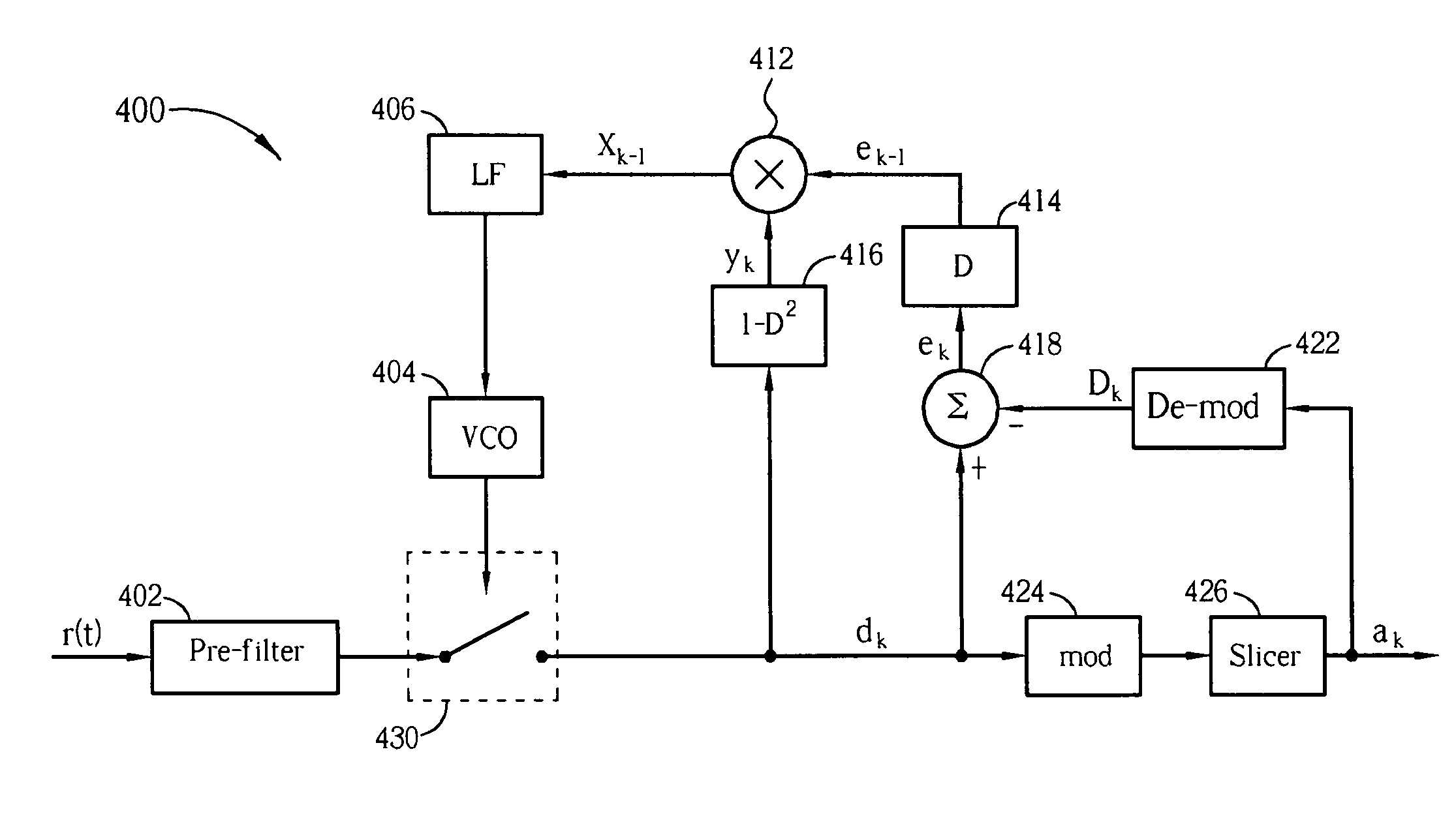
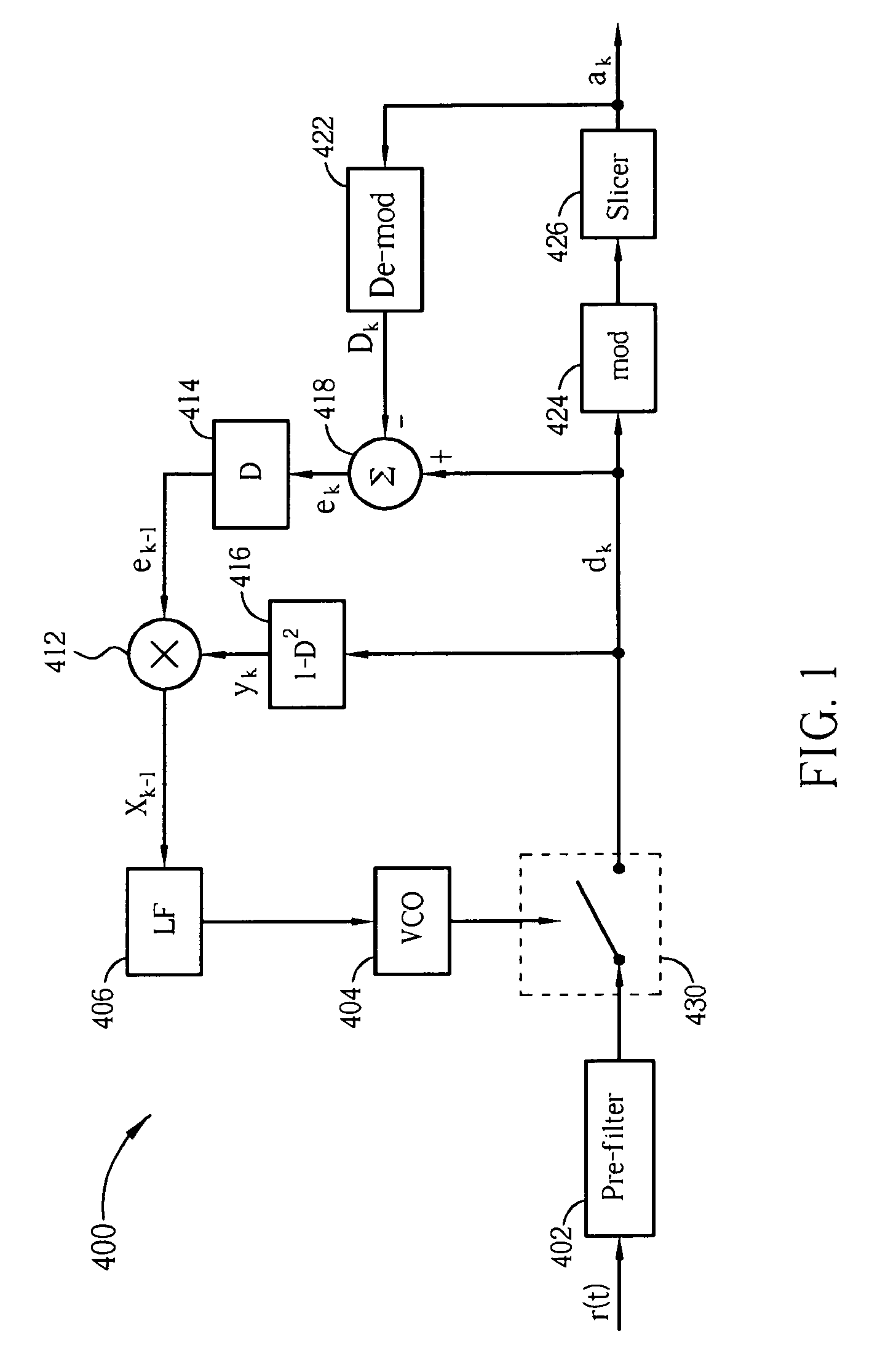
[0018]Please refer to FIG. 1, which is a diagram of a communication system 400, which takes modulo input signals as datum points and applies the Minimum Mean-Square Error (MMSE) algorithm, for implementing timing recovery according to a preferred embodiment of the present invention. As shown in FIG. 1, the communication system 400 includes a pre-filter 402, a swi...


PUM


Abstract

In the implementation of timing recovery in conventional communication systems, significant errors are generated from modulo operations under certain extreme conditions by taking input signals of a slicer as datum points. In order to prevent such errors, the input signal of a modulo processing circuit is taken as the datum point in place of the input signal of a slicer. This technique could also be applied to communication systems adopting the minimum mean-square error algorithm, the zero-forcing algorithm, or other relevant algorithms.

Description

BACKGROUND OF THE INVENTION[0001]1. Field of the Invention[0002]The present invention relates to a timing recovery circuit and a timing recovery method, and more particularly, to a timing recovery circuit and a timing recovery method of taking a modulo input signal as a datum point for implementing timing recovery.[0003]2. Description of the Prior Art[0004]In certain communication systems, a technique named Tomlinson-Harashima precoding (THP) is utilized at the transmitting terminals of the communication systems for implementing timing recovery. For example, THP may be utilized in communication systems based on 10G Base-T Ethernet applied with IEEE 802.3an. THP includes placing a feedback filter of a decision feedback equalizer at a transmitting terminal of a communication system instead of at a receiving terminal of the communication system for reducing error propagation resulted from symbol errors of a slicer in advance. However, for restricting symbol values of signals at the tra...

Claims


Application Information

Patent Timeline
04 Sep 2012
Publication
US8259883B2
IPC
H04L7/00
CPC
H04L7/0062
Inventors
HUANG, LIANG-WEI; SHIH, CHIH-YUNG