
Image processing device for vehicle

a technology for processing devices and vehicles, applied in the direction of image analysis, instruments, computing, etc., can solve the problems of inefficient processing, inability to recognize objects properly, and inability to accurately match changes in template images to objects

Inactive Publication Date: 2012-09-04
MAZDA MOTOR CORP
View PDF21 Cites 11 Cited by
  • Summary
  • Abstract
  • Description
  • Claims
  • Application Information

AI Technical Summary

Benefits of technology

[0004]The present invention has been devised in view of the above-described problems, and an object of the present invention is to provide an image processing device for a vehicle which can recognize the object efficiently and precisely.
[0007]According to an embodiment of the present invention, the image processing device for a vehicle further comprising a move-amount calculating means for calculating a move amount of the image picking-up means relative to the object, and a distance calculating means for calculating a distance between the object and the image picking-up means, wherein the transformation matrix calculating means calculates the transformation matrix in a manner of an analogous transformation matrix, affine transformation matrix, or projective transformation matrix in accordance with the move amount which is calculated by the move-amount calculating means and the distance which is calculated by the distance calculating means at the time the second image is picked up. Thereby, the calculation load of the transformation matrix calculating processing can be made properly low, and the transformation template can be created with the proper transformation matrix, thereby detect the object precisely.
[0008]According to another embodiment of the present invention, the transformation matrix calculating means calculates the transformation matrix in a manner of the projective transformation matrix when the move amount is greater than a specified amount and the distance is a specified distance or smaller. Thereby, the transformation template which is suitable to the precise matching for the object image can be obtained. This is because in general the view of the object image is distorted in a fan shape in case the camera's move amount is great and the object is located near. Accordingly, selecting the projective transformation matrix may be the best in this case.
[0010]According to another embodiment of the present invention, the transformation matrix calculating means calculates the transformation matrix in a manner of the analogous transformation matrix when the move amount is the specified amount or smaller and the distance is greater than the specified distance. Thereby, the transformation template which is suitable to the precise matching for the object image can be obtained. This is because in general the view of the object image is distorted in an analogous shape in case the object is located far and the camera's move amount is small. Accordingly, selecting the analogous transformation matrix may be the best in this case.
[0011]According to another embodiment of the present invention, the image processing device for a vehicle further comprising a move-amount estimating means for estimating the move amount of the image picking-up, and a three-dimension coordinates-value calculating means for calculating a three-dimension coordinates value of vehicle surroundings by using the first and second images picked up, wherein the move-amount calculating means calculates the move amount of the image picking-up means relative to the object by using a feature in the first image, which is extracted from the first image, and a corresponding point in the second image which corresponds to the feature in the first image, which is extracted from the second image, and the extraction of the corresponding point is executed in such a manner that a predicted position of the corresponding point in the second image which is calculated based on the move amount estimated by the move-amount estimating means, a search area in the second image for extracting the corresponding point is determined having a center of the search area which is located at the predicted position calculated, and the corresponding point is extracted from the search area determined Thereby, since the search area for extracting the corresponding point is determined based on the move amount estimated by the move-amount estimating means, the calculation load can be reduced by the determination of the search area in the matching processing. Further, since the search area is restricted, the mismatching can be prevented, thereby providing the accurate calculation of the move amount.
[0012]According to another embodiment of the present invention, the image processing device for a vehicle further comprising a feature-point selecting means for selecting specified numbers of feature points of the feature, wherein the move-amount calculating means calculates the move amount of the image picking-up means relative to the object by using the specified numbers of feature points of the future and corresponding points which correspond to the feature points, and the feature-point selecting means selects the feature points in such a manner that the numbers of epipolar lines which are determined by the selected feature points have a large angle therebetween. Thereby, the feature points can be distributed easily in a range which expands in a perspective direction or the like in the three-dimension space. Accordingly, the accuracy of the calculation of the move amount of the image picking-up means by the move-amount calculating means can be improved.

Problems solved by technology

However, the devices disclosed in the above-described first and second publications have some problem in that even though the template image was changed with the rotation or expansion / reduction, this changed template image could not be matched precisely to the object image in case the view of the object image was distorted in the frame image due to positional relationships between the image picking-up means and the object.
Thus, the object could not be recognized properly by these devices.
In this case, however, there is another problem in that the processing would be inefficient and the calculation load would be too high.
Further, in case the matching processing is executed with relationships of the image features like the device of the above-described third publication, there is further another problem in that the precise matching could not be obtained for the object image with the above-described distorted view.
Also, it could be difficult to precisely recognize objects which are different from each other in the kind but have analogous views.
Moreover, the method of the above-described last publication has some problem in that since the image transformation is conducted by stages and the selection of the best transformation is conducted by the evaluation index (geometrical AIC), the processing would be inefficient and the calculation load would be too high.

Method used


Image

  • Image processing device for vehicle
  • Image processing device for vehicle
  • Image processing device for vehicle

Examples


embodiment 1

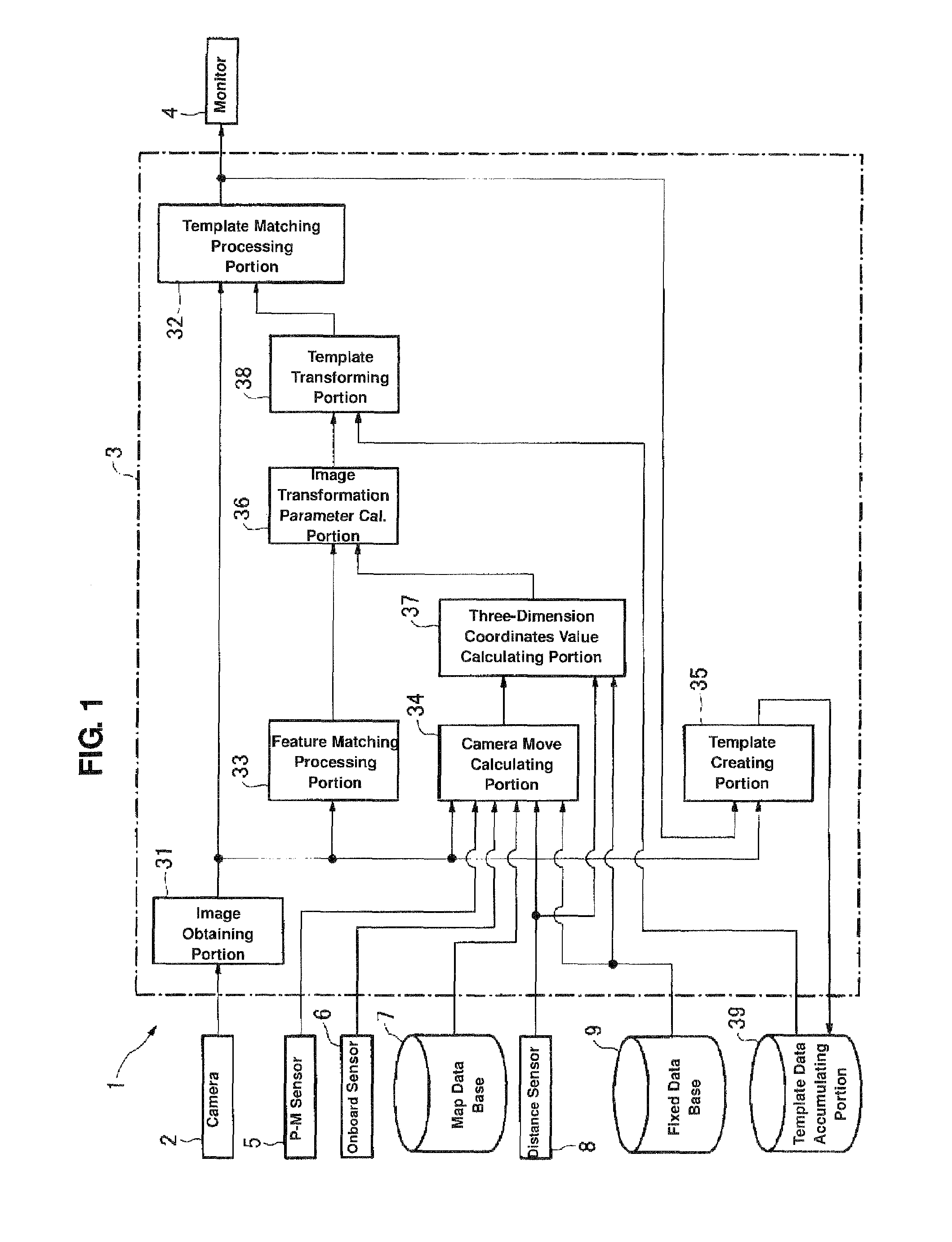
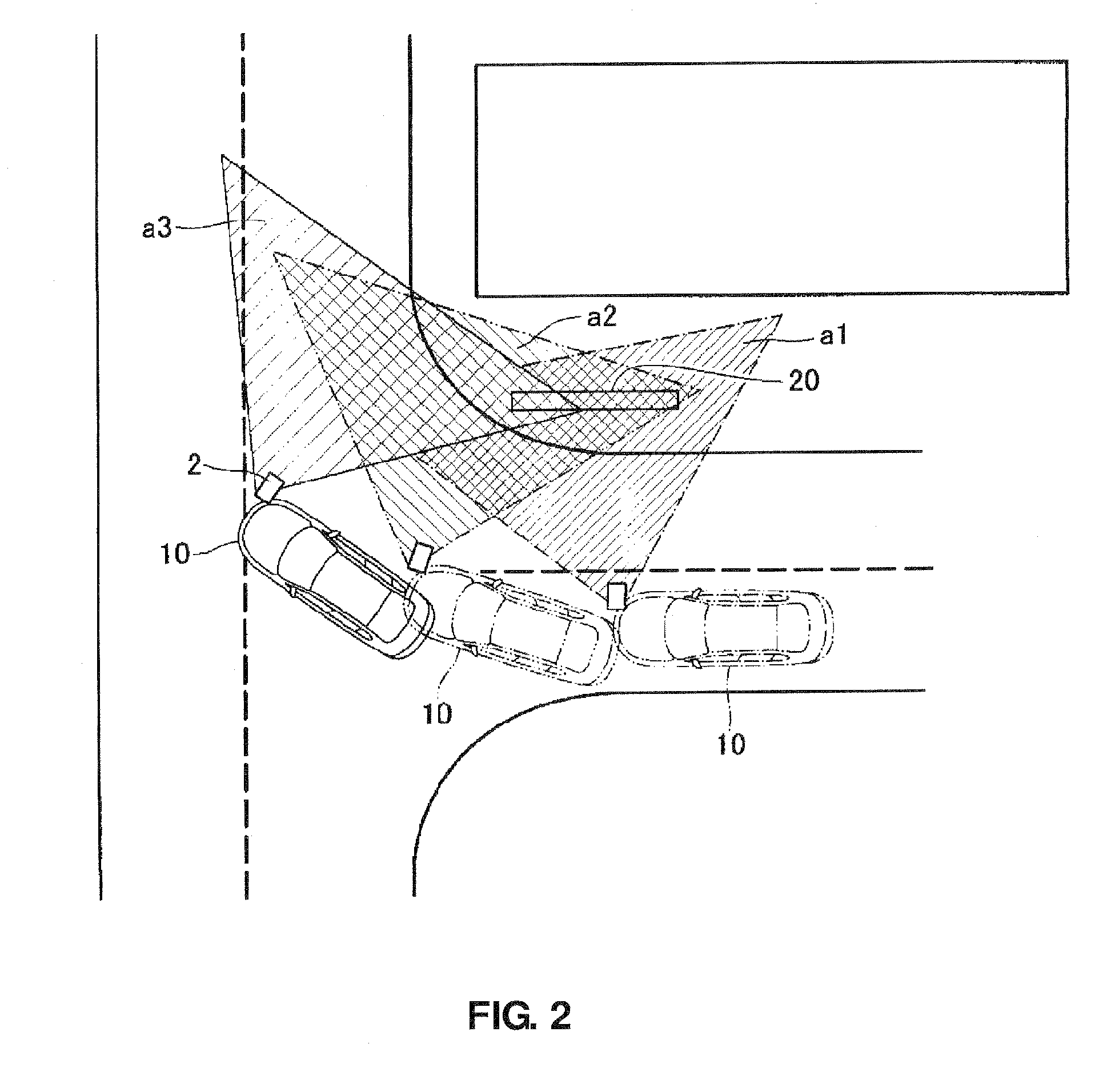
[0037]A first embodiment will be described referring to FIGS. 1 through 13. An image processing device for a vehicle 1 of the present embodiment comprises, as shown in FIG. 1, a camera 2, a controller 3, a monitor 4, a position measuring sensor 5, an onboard sensor 6, a map data base 7, a distance sensor 8, and a fixed data base 9. The camera 2, which is an image picking-up means, such as a CCD camera or a CMOS camera, is installed in a vehicle 10 at a specified level so as to face to the right side of the vehicle, for example (see FIG. 2). The camera 2 picks up an image on the vehicle's right with a specified frame rate. This frame image picked up is outputted to the controller 3. The monitor 4, which is an indicating device such as LCD, indicates the frame image from the controller 3 for a driver. The position-measuring sensor 5, which is a sensor to measure vehicle position-measuring data, such as GPS or INS, outputs its position-measuring data to the controller 3. Position-measu...

embodiment 2

[0087]Hereinafter, a second embodiment of the present invention will be described referring to FIGS. 14 through 21. The same means or components as those in the above-described first embodiment are denoted by the same reference characters, and their detailed descriptions are omitted here. The present embodiment is substantially an alternative of part of the first embodiment which is shown with the flowchart of FIG. 5.

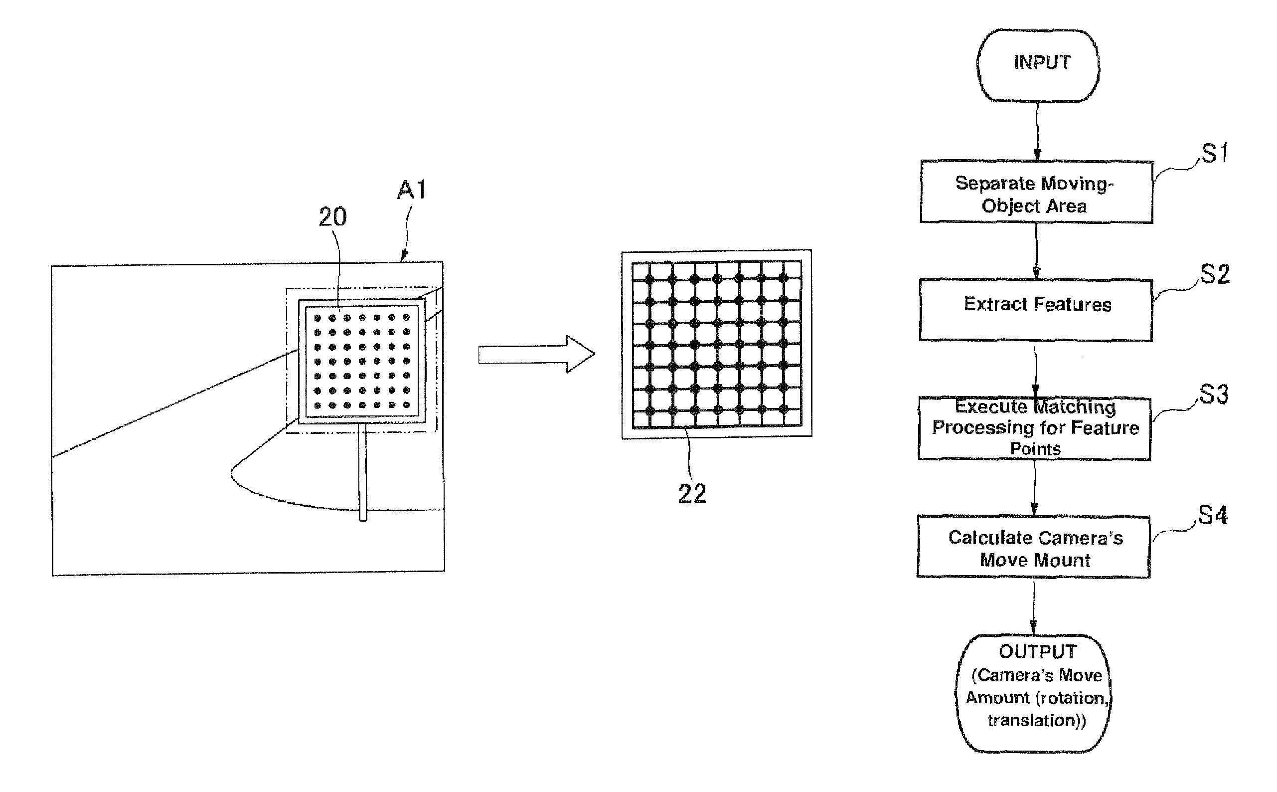
[0088]In the present embodiment, a controller 3′ of an image processing device 1′ for a vehicle comprises the image obtaining portion 31, a moving-object area separating portion 52, a search-area setting portion 53, a feature-point extraction selecting portion 54, the feature matching processing portion 33, the camera move calculating portion 34, the three-dimension coordinates-value calculating portion 37, and a camera move estimating portion 58. The controller 3′ further comprises a three-dimension data accumulating portion 59 as a memory means which comprises a memor...


PUM


Abstract

An image processing device comprising a camera to pick up frame images at the times, a basic template creating portion to create a basic template of a picked-up object in the first image, an image transformation parameter calculating portion to calculate a transformation matrix to execute an image transformation of an object of the first image to an object of the second image, a template transforming portion to create a transformation template by transforming the basic template with the transformation matrix, and a template matching processing portion to execute a template matching processing to the second image with the transformation template to detect the object and to determine that the picked-up object in the second image is identical to the basic template when a matching degree by the matching means is higher than a specified degree.

Description

BACKGROUND OF THE INVENTION[0001]The present invention relates to an image processing device for a vehicle, and in particular, relates to an image processing device for a vehicle which recognizes an object in an image by an image recognition processing with a template.[0002]Conventionally, technologies of an image recognition of any object (road signs and the like) in a picked-up image picked by using a template image which has been prepared previously are known (see the following publications, for example). According to the device disclosed in U.S. Patent Application Publication No. 2008 / 0000289 A1, a so-called template matching processing is executed for the image data of road signs picked up with the template image of the road signs. Herein, the pattern matching is conducted by rotating the template image continuously by a specified angle. In the device of the above-described publication, it is determined that the matching is complete when the matching degree has exceeded a speci...

Claims


Application Information

Patent Timeline
Patent Type & Authority Patents(United States)
IPC IPC(8): G06K9/00
CPCG06K9/00791G06T7/004G06T7/20G06T7/70G06V20/56
Inventor OKUGI, TOMOKAZUCHIBA, MASAKI
Owner MAZDA MOTOR CORP
Learn More