Apparatus for calculating state of charge, method of calculating state of charge, and electric system

a technology for calculating the state of charge and the apparatus, applied in the direction of battery/fuel cell control arrangement, instruments, transportation and packaging, etc., can solve the problem of difficult to distinguish between the cases, difficult to determine that the electric power to be charged needs to be limited, and shorter distance that the vehicle can run on a single charg

Active Publication Date: 2012-09-04
TOYOTA JIDOSHA KK
View PDF7 Cites 0 Cited by
  • Summary
  • Abstract
  • Description
  • Claims
  • Application Information

AI Technical Summary

Benefits of technology

[0014]According to this structure, when the sum of the first state of charge of the first power storage device and the second state of charge of the second power storage device is large, the first coefficient and the second coefficient are set in accordance with the higher state of charge. The product of the higher state of charge and the first coefficient is added to the product of the lower state of charge and the second coefficient, to thereby calculate the state of charge of the power storage system. Since the first coefficient is higher than the second coefficient, the state of charge of the power storage system is calculated to be relatively high in accordance with the higher state of charge. In contrast, when the sum of the first state of charge of the first power storage device and second state of charge of second power storage device is small, the first coefficient and the second coefficient are set in accordance with the lower state of charge. The product of the lower state of charge and the first coefficient is added to the product of the higher state of charge and the second coefficient, to thereby calculate the state of charge of the power storage system. Since the first coefficient is higher than the second coefficient, the state of charge of the power storage system is calculated to be relatively low in accordance with the lower state of charge. This enables calculation of the total state of charge taking into consideration the difference between the states of charge of the respective power storage devices.
[0016]According to this structure, when the arithmetic average value of the first state of charge and the second state of charge is larger than or equal to the predetermined second value, the state of charge of the power storage system is calculated to be relatively high. In contrast, when the arithmetic average value of the first state of charge and the second state of charge is smaller than the second value, the state of charge of the power storage system is calculated to be relatively low. This enables early detection that the state of charge is high when the arithmetic average value of the first state of charge and the second state of charge is larger than or equal to the second value, and enables early detection that the state of charge is low when the arithmetic average value of the first state of charge and the second state of charge is smaller than the second value.
[0018]According to this structure, when the selected state of charge falls within the predetermined range where the second value is centered, the first coefficient and the second coefficient are equal. Therefore, if both the first state of charge and the second state of charge fall within the predetermined range when the selected state of charge is changed, the calculated state of charge of the power storage system can be equal before and after the selected state of charge is changed. This can ensure continuousness of the calculated state of charge of the power storage system.
[0020]According to this structure, the first coefficient and the second coefficient are set to be equal by correcting the selected state of charge so as to fall within the predetermined range even if the selected state of charge falls outside the predetermined range. Therefore, by correcting the selected state of charge so as to fall within the predetermined range even if both the first state of charge and the second state of charge fall outside the predetermined range when the selected state of charge is changed, the calculated state of charge of the power storage system can be equal before and after the selected state of charge is changed. This can ensure continuousness of the calculated state of charge of the power storage system.
[0022]According to this structure, when the sum of the first state of charge of the first power storage device and the second state of charge of the second power storage device is large, the state of charge of the power storage system is calculated to be higher as the higher state of charge is closer to the upper limit value. In contrast, when the sum of the first state of charge and the second state of charge is small, the state of charge of the power storage system is calculated to be lower as the lower state of charge is closer to the lower limit value. This allows the calculated state of charge to show that one state of charge is close to the upper limit value or the lower limit value.

Problems solved by technology

One problem with the electric vehicle lies in that the distance that the vehicle can run on a single charge is shorter than in a vehicle having an internal combustion engine as a driving source.
Another problem with the electric vehicle is to protect a power storage device against overdischarging and overcharging.
However, calculating a simple total sum of the states of charge of the respective power storage devices as the total state of charge of the power storage system will make it difficult to distinguish between the case where the respective power storage devices have different states of charge and the case where the two power storage devices have an equal state of charge.
It may therefore be difficult to determine that electric power to be charged needs to be limited.
However, calculating a simple total sum of the states of charge of the respective power storage devices as the total state of charge of the power storage system will make it difficult to distinguish between the case where the respective power storage devices have different states of charge and the case where the two power storage devices have an equal state of charge.
It may therefore be difficult to determine that electric power to be discharged needs to be limited.

Method used


Image

  • Apparatus for calculating state of charge, method of calculating state of charge, and electric system
  • Apparatus for calculating state of charge, method of calculating state of charge, and electric system
  • Apparatus for calculating state of charge, method of calculating state of charge, and electric system

Examples


Embodiment Construction

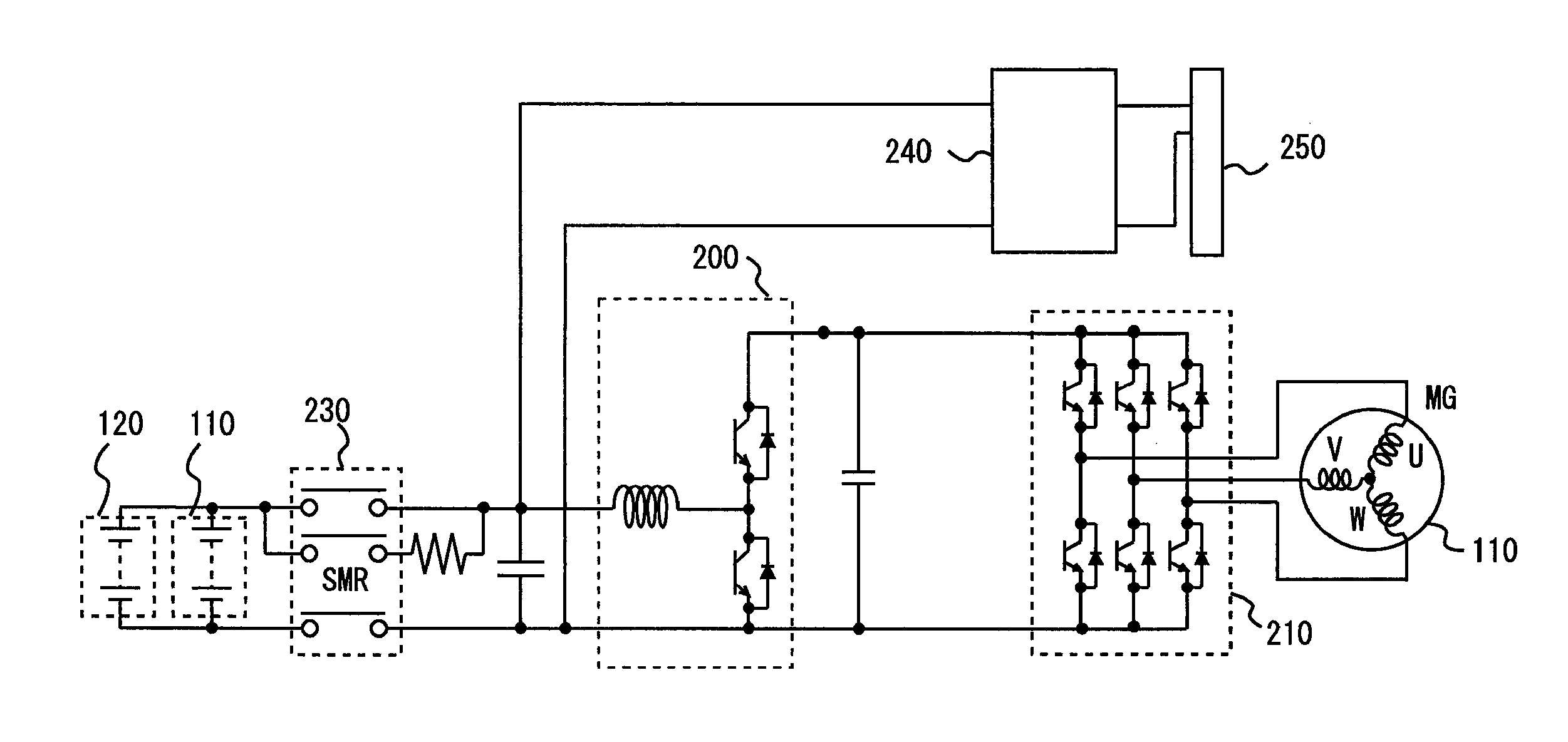
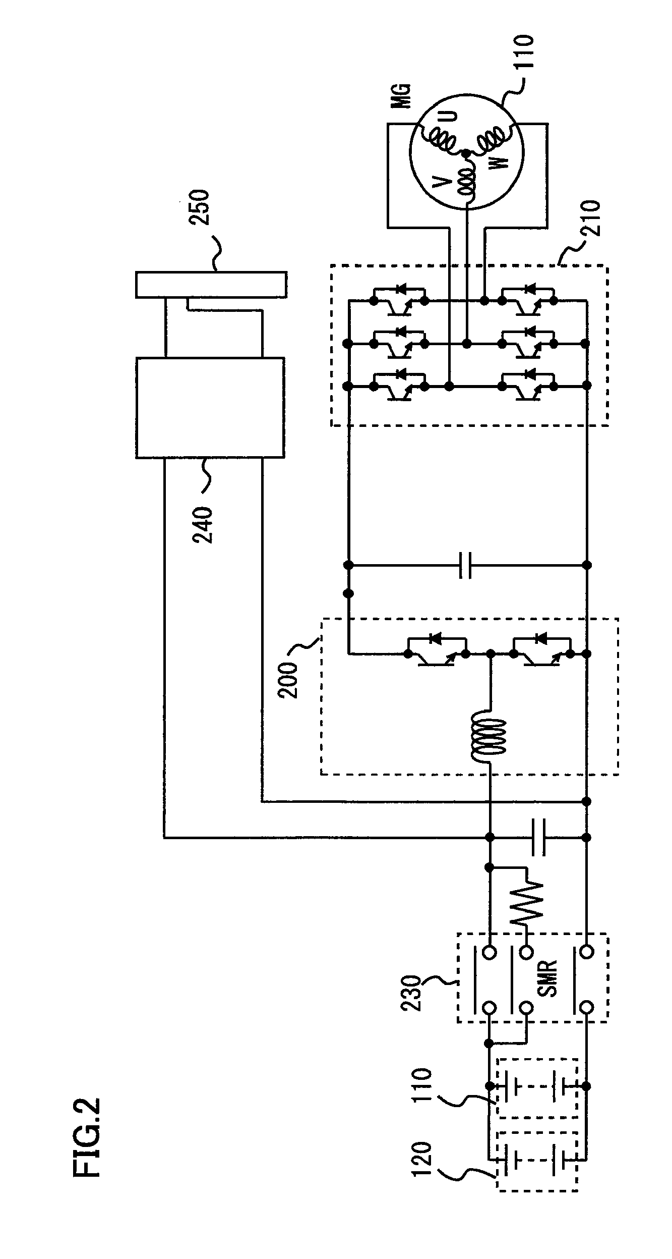
[0040]The embodiments of the present invention will be hereinafter described with reference to the accompanying drawings, in which the same components are designated by the same reference characters. Names and functions thereof are the same, and therefore, description thereof will not be repeated.

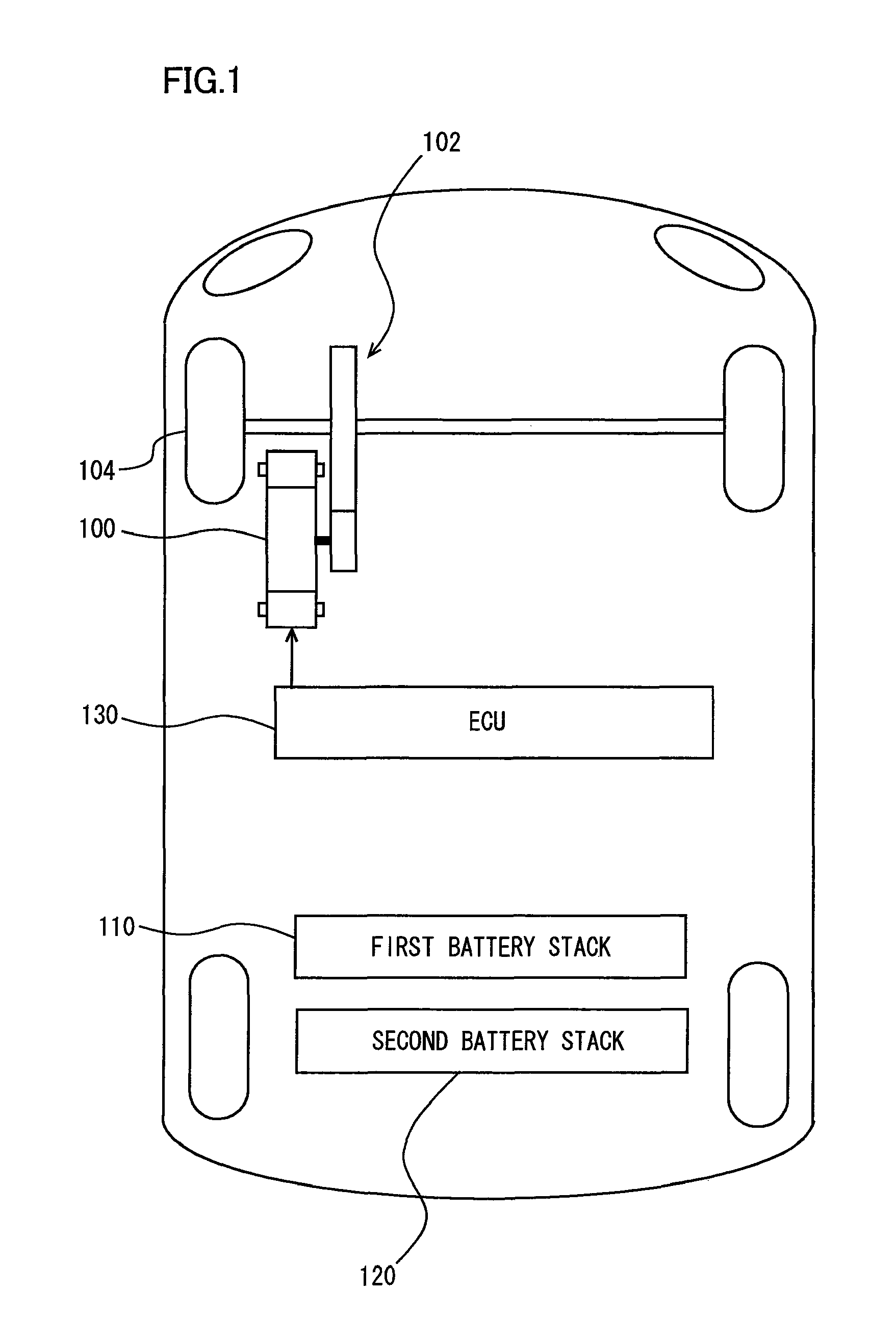
[0041]Referring to FIG. 1, an electric vehicle will be described. This electric vehicle is equipped with an electric motor 100, a first battery stack 110 and a second battery stack 120. The electric vehicle runs using electric motor 100 as a driving source supplied with electric power from first battery stack 110 and second battery stack 120. A hybrid vehicle equipped with an internal combustion engine in addition to electric motor 100 may be employed instead.

[0042]Electric motor 100 is controlled by an ECU (Electronic Control Unit) 130. ECU 130 may be divided into a plurality of ECUs.

[0043]Electric motor 100 is a three-phase alternating-current rotating electric machine having a U-phase co...


PUM


Abstract

When the sum of a first state of charge of a first battery stack and a second state of charge of a second battery stack is large, a higher state of charge is selected as a priority state of charge. When the sum of first state of charge of the first battery stack and the second state of charge of the second battery stack is small, a lower state of charge is selected as the priority state of charge. A first coefficient and a second coefficient are set in accordance with the priority state of charge. The second coefficient is set so as to be lower than the first coefficient. The product of the first coefficient and the priority state of charge is added to the product of the second coefficient and the other state of charge, to thereby calculate a state of charge of a power storage system.

Description

[0001]This nonprovisional application is based on Japanese Patent Application No. 2010-094156 filed on Apr. 15, 2010 with the Japan Patent Office, the entire contents of which are hereby incorporated by reference.BACKGROUND OF THE INVENTION[0002]1. Field of the Invention[0003]The present invention relates to an apparatus for calculating a state of charge, and more particularly to a technique of calculating a state of charge of a power storage system provided with a first power storage device and a second power storage device.[0004]2. Description of the Background Art[0005]Conventionally, an electric vehicle equipped with an electric motor as a driving source is known. Such a vehicle is equipped with a power storage device that stores electric power, such as a battery and a capacitor. Electric power stored in the power storage device is supplied to the electric motor. The electric motor is controlled so as to output desired power.[0006]One problem with the electric vehicle lies in th...

Claims


Application Information

Patent Timeline
Patent Type & Authority Patents(United States)
IPC IPC(8): G06F19/00
CPCB60L11/1861G01R31/3606G01R31/3648B60L2230/12Y02T90/12Y02T10/705Y02T90/121Y02T10/7044Y02T10/7088Y02T10/7005B60L53/18B60L58/12G01R31/382Y02T10/70Y02T10/7072Y02T90/14
Inventor YAMAMOTO, MASAYASETA, ITARU
Owner TOYOTA JIDOSHA KK
Why Eureka
Try Eureka