
Connection tool with indexing system

a technology of indexing system and connection tool, which is applied in the direction of sealing/packing, mechanical equipment, and borehole/well accessories, etc., can solve the problems of damage to the connection structure or other installations, difficulty in accurately controlling the operation and difficulty in controlling the accuracy of simultaneous horizontal and vertical movements

Active Publication Date: 2012-09-18
AFGLOBAL UK LTD
View PDF9 Cites 20 Cited by
  • Summary
  • Abstract
  • Description
  • Claims
  • Application Information

AI Technical Summary

Benefits of technology

"The invention provides a connection tool for connecting a pipeline to a subsea connection structure, which includes a connection porch and at least one locating post. The tool comprises a tool chassis, a carrier for carrying the pipeline, and a locating member positioned at the front of the chassis. The locating member includes a locking member that engages the locating post to hold the tool in position relative to the connection porch. The tool can be maneuvered to engage the locating post and prevent disengagement, and then disengaged and maneuvered away from the connection structure. The method involves engaging the locating post with the locating member, maneuvering the tool to align the pipeline with the connection porch, connecting the pipeline to the connection porch, and then disengaging the locating member from the locating post. The technical effect of the invention is to provide a reliable and efficient tool for connecting pipelines to subsea connection structures."

Problems solved by technology

Manoeuvres that require simultaneous horizontal and vertical movements are more difficult to control accurately.
However, when lifting the tool off the locating posts at the end of the connection process, problems can occur if the load of the connection tool is not appropriately distributed on the lifting mechanism.
If the load is incorrectly distributed, the connection tool can swing in an uncontrolled way as soon as the sleeves disconnect from the locating posts, potentially causing damage to the connection structure or other installations.

Method used


Image

  • Connection tool with indexing system
  • Connection tool with indexing system
  • Connection tool with indexing system

Examples


Embodiment Construction

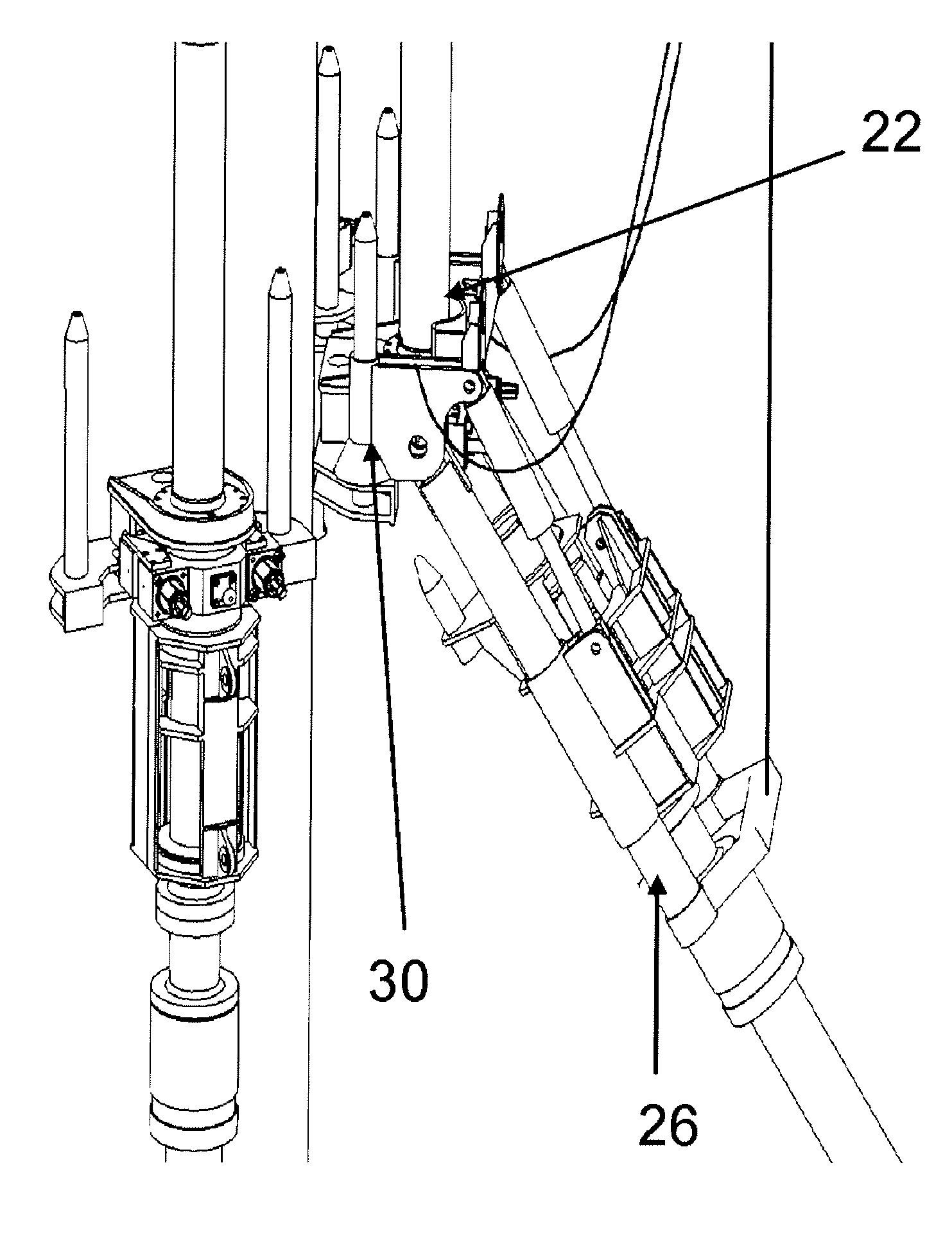
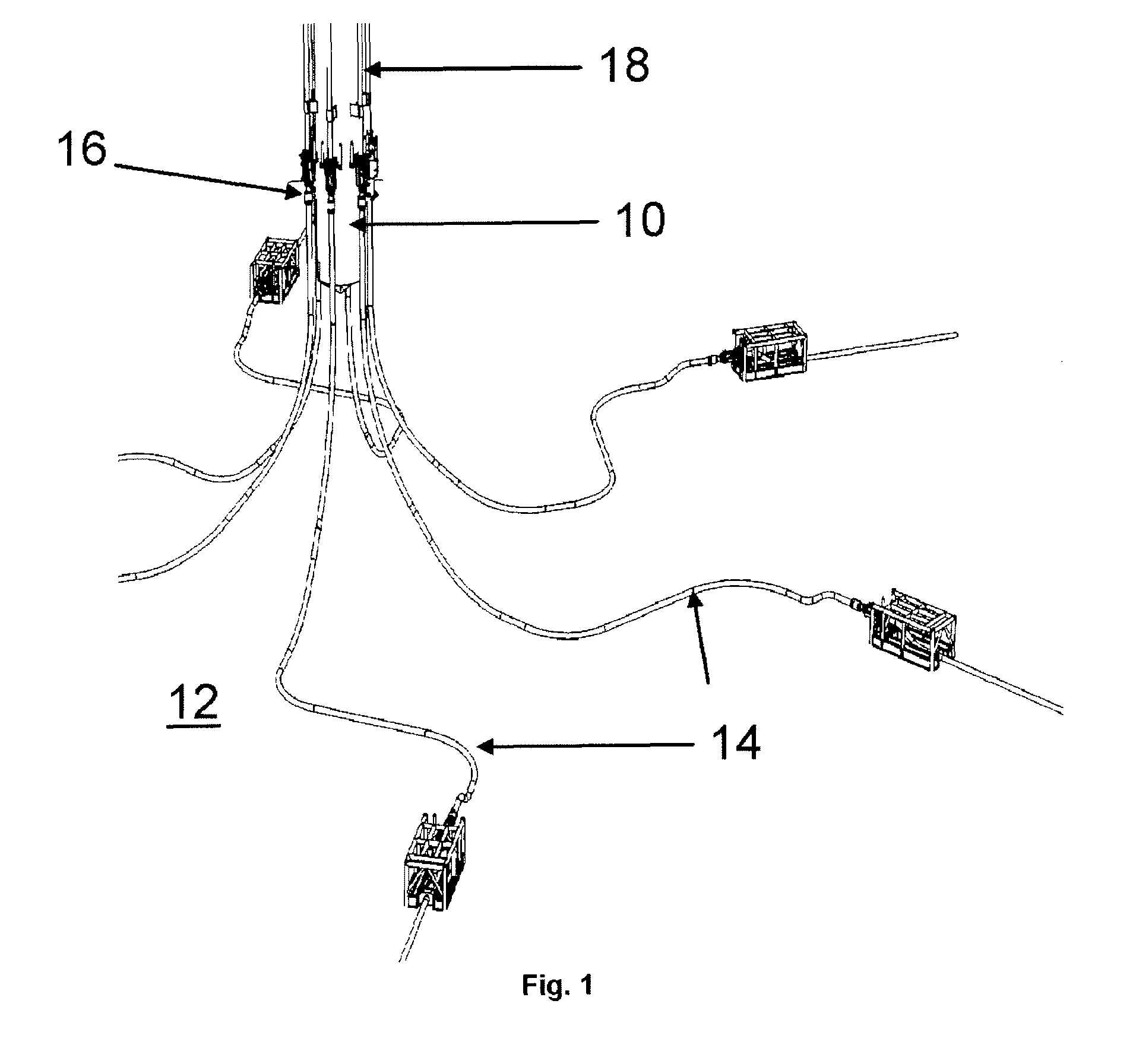
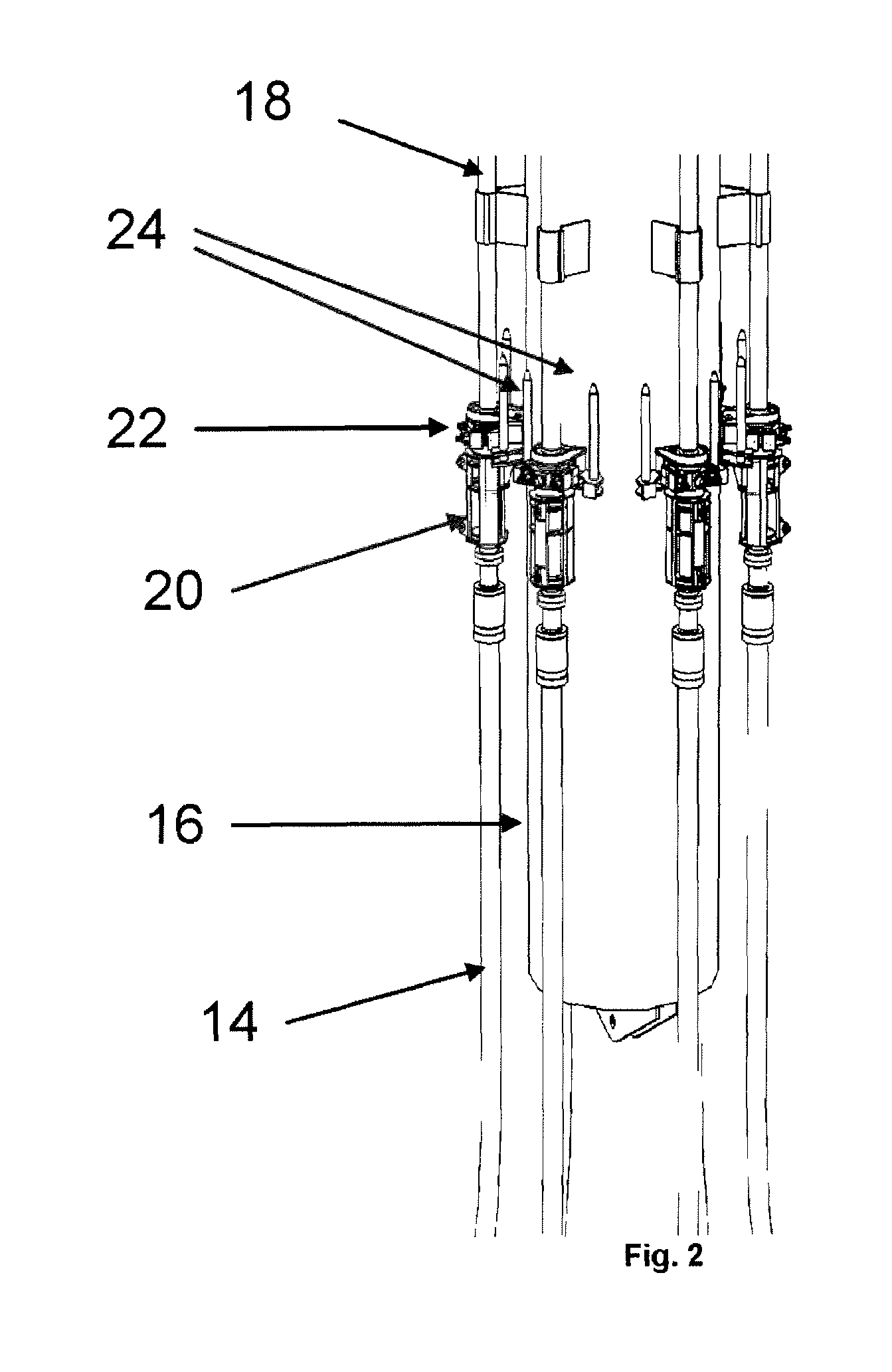
[0037]FIG. 1 shows a typical riser tower subsea installation for which the present invention can be used. The riser tower 10 is moored to the sea bed 12. Jumpers 14 running from the flowline termination assemblies (not shown) on the sea bed connect to the riser base 16, and flow conduits 18 run to the riser top where they connect to flexible risers extending to a surface production platform such as an FPSO (not shown). FIG. 2 shows more detail of the riser base 16. The jumpers 14 connect to the downward facing ends of the conduits 18 at a connection structure 20. The connection structure includes a connection porch 22 having a pair or upwardly extending location posts 24 on either side thereof.

[0038]To connect the jumper 14 to the connection 20, a connection tool is used. The connection tool is shown in FIGS. 3 and 4 and comprises a chassis 26 having a moveable carrier 28 mounted thereon. The carrier 28 is provided with a mechanism to releasably connect to the end of the jumper 14. ...


PUM


Abstract

A connection tool for connecting a pipeline to a subsea connection structure which includes a connection porch (22) into which the pipeline is connected, the tool comprising:—a tool chassis (26);—a carrier (28) mounted on the chassis (26) and adapted to releasably carry the pipeline;—at least one locating member (30) positioned at the front of the chassis (26) so as to be engageable with the locating posts (24) on the connection porch (22) to hold the chassis (26) adjacent to the connection porch (22), a hinge connecting the locating member (30) to the chassis (26), such that the azimuthal orientation of the chassis relative to the connection porch can be varied when the locating member (30) is engaged with the locating post, wherein the locating member (30) includes a locking member that engages the locating post when the locating member (30) is engaged thereon.

Description

TECHNICAL FIELD[0001]This invention relates to tools and methods for connecting pipelines to subsea connection structures such as those used in offshore oil and gas production fields. Typical uses include connection of pipelines to riser bases, flowline termination assemblies, manifolds and Christmas trees.BACKGROUND ART[0002]When connecting pipelines such as flowlines, jumpers and risers of either rigid or flexible construction (hereinafter ‘pipelines’) to subsea connection structures, a connection tool can be used which connects to the end of the pipeline and is then brought to the connection structure where it operates to make the connection between the pipeline and connection structure. Examples of such tools are the DMaC and FTC tools of VerdErg which are described on the Internet web site www.verderg.com.[0003]In the FTC system, a connection porch having one or more locating posts is provided at the connection structure (manifold, riser base, midwater riser, flowline terminati...

Claims


Application Information

Patent Timeline
Patent Type & Authority Patents(United States)
IPC IPC(8): E21B43/013
CPCE21B43/0107E21B43/013F16L1/20F16L1/26
Inventor BUTCHER, DAVID JOHNWOOD, RICHARD JOHN
Owner AFGLOBAL UK LTD
Learn More