
Multistage centrifugal compressor

a centrifugal compressor and multi-stage technology, applied in the field of centrifugal compressors, can solve the problems of disadvantageous reduction of efficiency and difficult application of multi-stage centrifugal compressors, and achieve the effects of wide operating flow range, improved index of conflicting characteristics, and high efficiency

Inactive Publication Date: 2012-09-18
HITACHI IND PROD LTD
View PDF6 Cites 3 Cited by
  • Summary
  • Abstract
  • Description
  • Claims
  • Application Information

AI Technical Summary

Benefits of technology

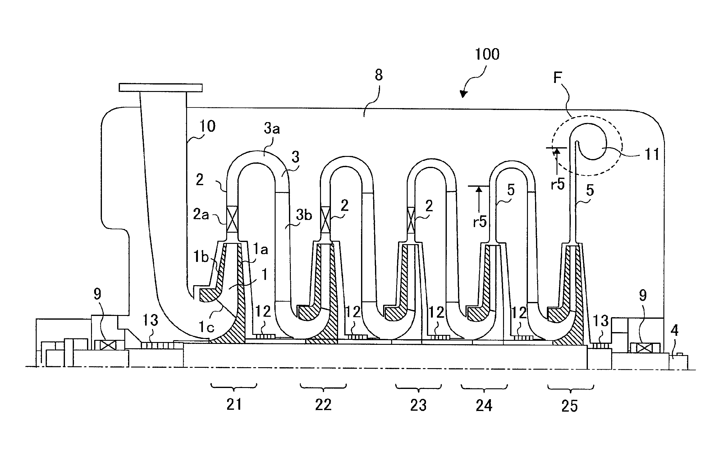
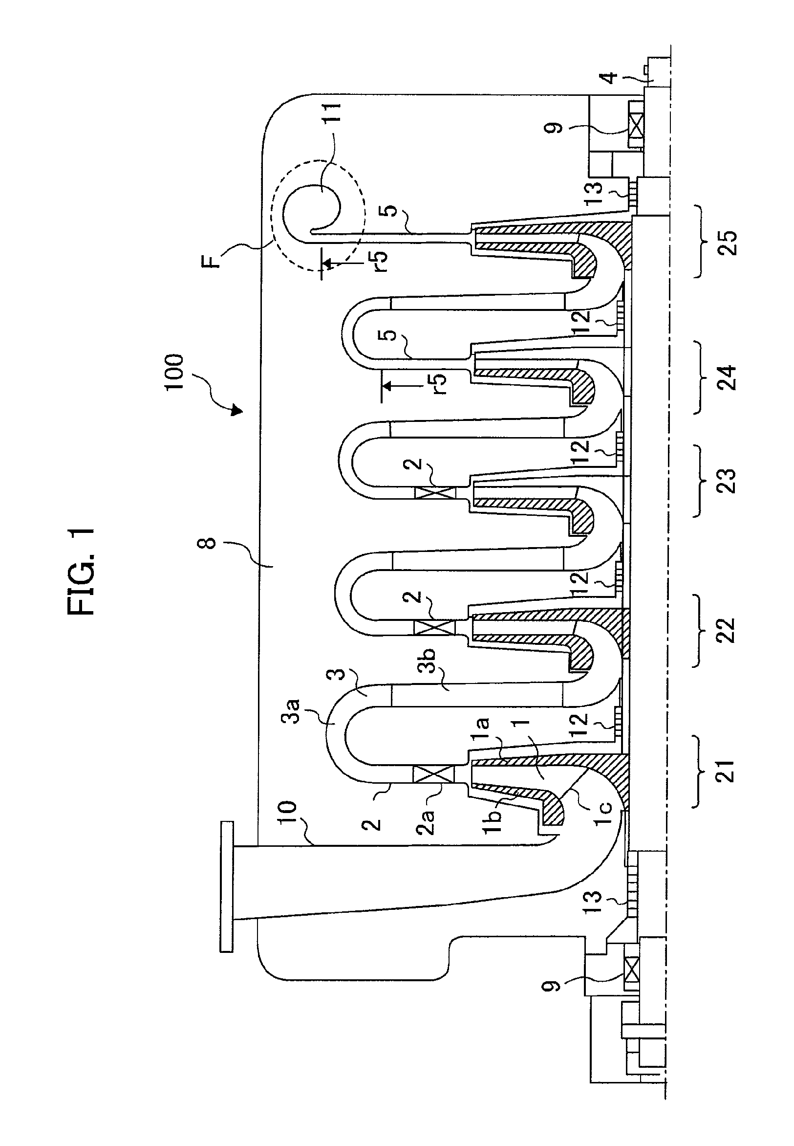
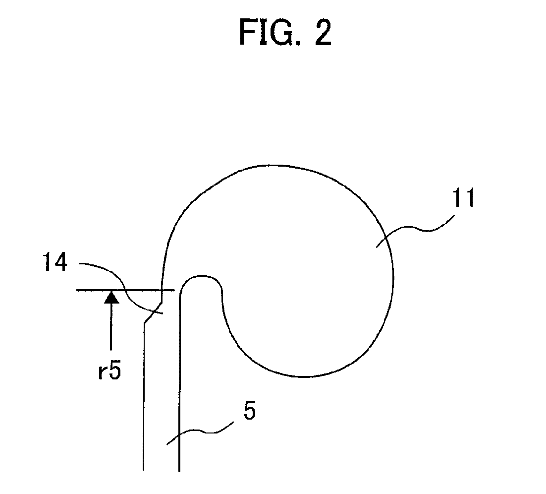
The present invention is a multistage centrifugal compressor that improves the performance of a compressor by achieving high efficiency and a wide operating flow range. The compressor includes multiple impellers attached to a shaft, with each compressor stage including a vanless diffuser and a vaned diffuser. The outlet blade angle and radius of the diffuser can be adjusted to optimize performance. The compressor stages are arranged in a continuous manner, and a narrowed channel width is used in the vanless diffuser at the last compressor stage. The use of vaned diffusers in the compressor stages allows for a wider operating flow range and improved efficiency. Overall, the invention provides a more effective and efficient multistage centrifugal compressor for industrial applications.

Problems solved by technology

If the vaneless diffusers are provided at all the compressor stages in the multistage centrifugal compressor, an operating flow range can be advantageously widened, whereas the efficiency is disadvantageously decreased.
However, since matching with the performance of the other compressor stages is not much considered, it is difficult to apply to the multistage centrifugal compressor.

Method used


Image

  • Multistage centrifugal compressor
  • Multistage centrifugal compressor
  • Multistage centrifugal compressor

Examples


Embodiment Construction

[0018]An example of a performance curve of each compressor stage in a centrifugal compressor including multiple stages is shown in FIG. 5. As being apparent from FIG. 5, if an operating point is moved in the direction where the volume flow of the first compressor stage is decreased in the centrifugal compressor, a head (pressure ratio) of the first compressor stage is increased. As a result, outlet pressure of the first compressor stage, namely, inlet pressure of the second compressor stage is increased. Since the pressure of the inlet is increased, an inlet fluid density becomes high at the second compressor stage.

[0019]That is, the decreased amount of the volume flow rate (equal to mass flow / inlet density) of the second compressor stage becomes larger than that of the first compressor stage. Thereafter, the decreased amount of the volume flow rate sequentially becomes larger towards the latter stages, and the decreased amount of the last compressor stage is maximized. For this rea...


PUM


Abstract

In a multistage centrifugal compressor, a plurality of impellers is attached to the same rotary shaft. Vaned Diffusers and vaneless diffusers are used, as diffusers, for respective compressor stages configuring the compressor. The vaned diffusers are continuously used from the first compressor stage to the middle compressor stage, and the vaneless diffusers are used for the last compressor stage and the previous stage. While high efficiency is maintained at the compressor stages having the vaned diffusers, an operating flow range is secured at the compressor stages having the vaneless diffusers.

Description

[0001]The present application claims priority from Japanese application JP2008-195817 filed on Jul. 30, 2008, the content of which is hereby incorporated by reference into this application.[0002]The present invention relates to a centrifugal compressor, and particularly to a multistage centrifugal compressor to which a plurality of centrifugal impellers are attached to the same shaft.[0003]An example of a conventional single-shaft multistage centrifugal compressor is described in Japanese Patent Application Laid-Open No. 2006-63895. As described in Japanese Patent Application Laid-Open No. 2006-63895, a plurality of centrifugal impellers are attached to one rotary shaft in a general multistage centrifugal compressor. In addition, a diffuser is provided on the downstream side of each impeller, and a return channel is provided on the downstream side of each diffuser. The impeller, the diffusers and the return channel (except the last stage) configure compressor stage. A suction nozzle...

Claims


Application Information

Patent Timeline
Patent Type & Authority Patents(United States)
IPC IPC(8): F04D29/44
CPCF04D17/122F04D29/444F04D29/441
Inventor NISHIDA, HIDEOKOBAYASHI, HIROMITANAKA, MASANORIKUWANO, TETSUYAITOU, TOSHIOSHIBATA, TAKANORIYAGI, MANABU
Owner HITACHI IND PROD LTD
Learn More