Optical sensor device

a sensor device and optical sensor technology, applied in the direction of optical radiation measurement, vehicle cleaning, instruments, etc., can solve the problems of reducing the useful luminous efficiency of the device, requiring a large amount of space, and reducing the useful luminous efficiency and sensitivity to stray light, so as to achieve excellent directional effect and minimal space requirement

Active Publication Date: 2012-09-18
TRW AUTOMOTIVE ELECTRONICS & COMPONENTS GMBH & CO KG
View PDF27 Cites 18 Cited by
  • Summary
  • Abstract
  • Description
  • Claims
  • Application Information

AI Technical Summary

Benefits of technology

[0010]In this case a pencil of rays impinging parallely on the pane passes through it at an angle and is then coupled into the lens plate by the Fresnel reflector structure and directed perpendicularly through the lens plate onto the combined Fresnel structure and focused on the light receiver by the other combined Fresnel structure. Here, too, all optically active elements are concentrated in the lens plate, so that a minimum space requirement is obtained. At the same time, an excellent directional effect is achieved for the light to be detected.

Problems solved by technology

These sensors are based on the principle of light diffraction with the aid of diffractive elements and therefore have the principle-induced drawback of a substantially lower useful luminous efficiency and a higher sensitivity to stray light.
But since the surfaces of the light conductor in which the lenses are configured are perpendicular to the surface of the pane, this device requires a very large amount of space.
The basic disadvantages of prior art optical rain sensor or daylight sensor devices are found in the high production expense and in the unfavorable ratio of the sensor dimensions to the size of the use-sensitive surface area.

Method used


Image

  • Optical sensor device
  • Optical sensor device
  • Optical sensor device

Examples


Embodiment Construction

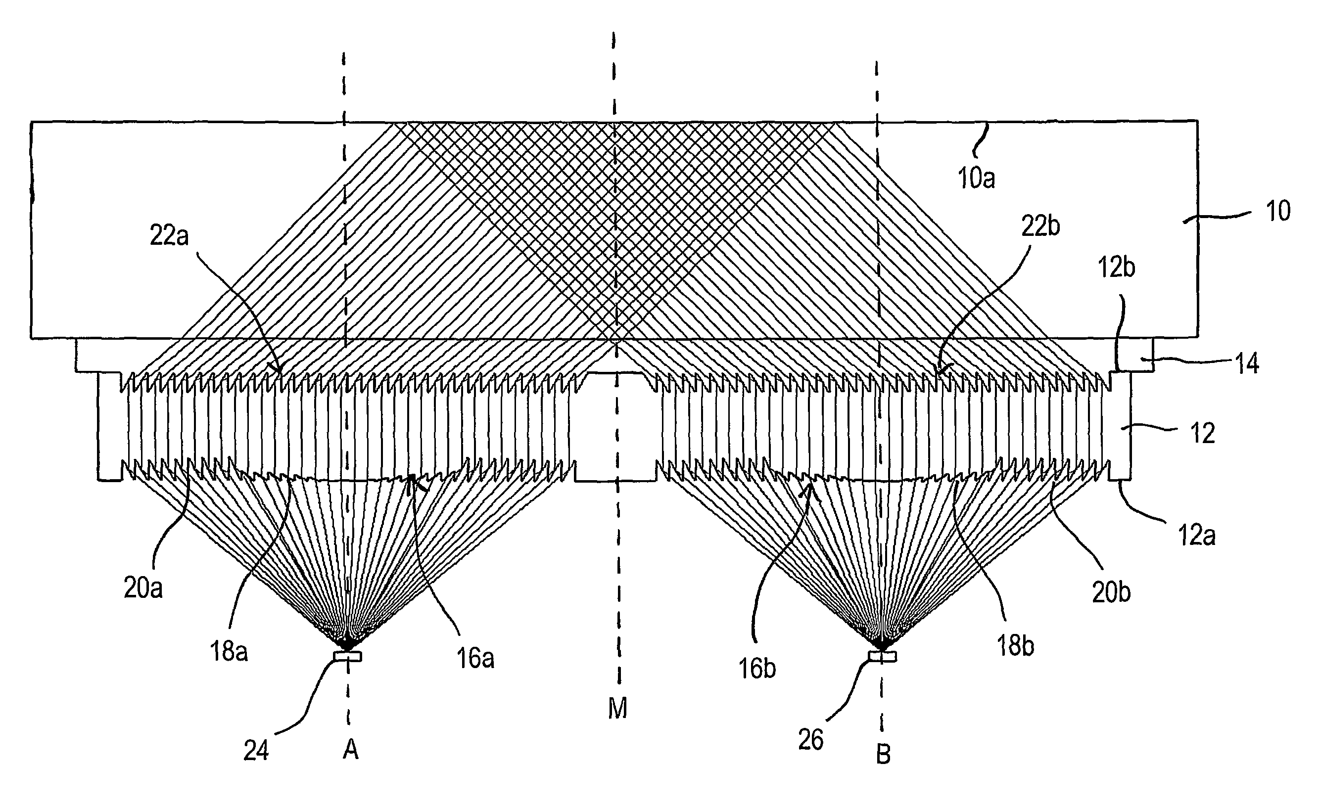
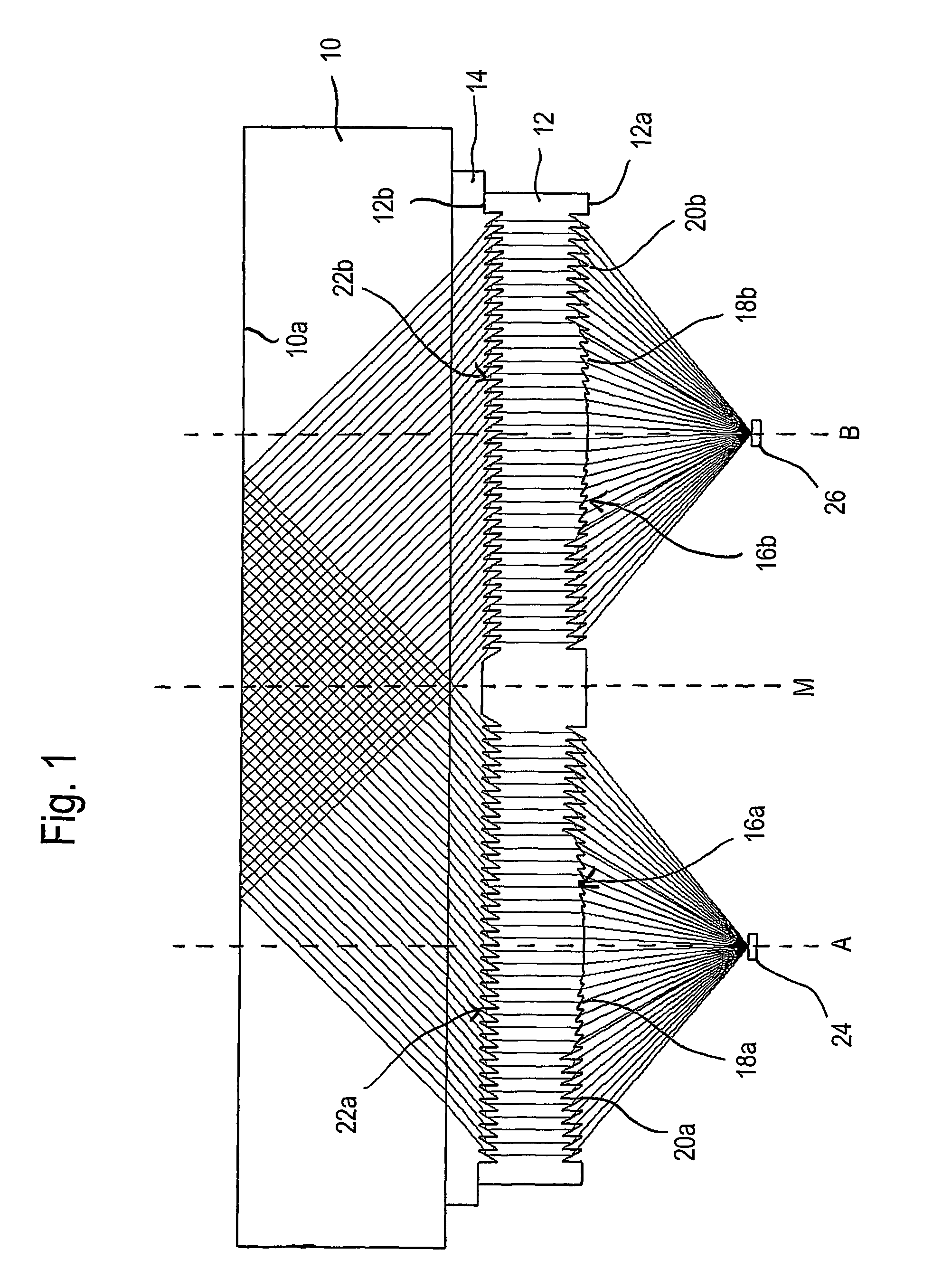
[0018]A rain sensor is typically comprised of two identical optical sensor units. A sensor unit of this type is schematically illustrated in FIG. 1. The sensor unit is attached to the windshield 10 of a motor vehicle. The optically active element of the sensor unit is a lens plate 12. The lens plate 12 is optically coupled to the windshield 10 by means of a coupler layer 14.

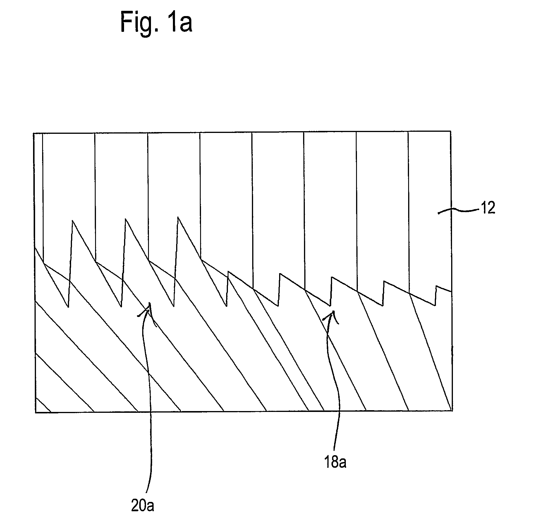
[0019]On a first surface 12a facing away from the windshield 10, the lens plate 12 is provided with two identical Fresnel structures 16a, 16b, which are arranged at a small distance from each other. Both Fresnel structures 16a, 16b are designed to be rotationally symmetrical with respect to an axis A and B, respectively. The Fresnel structures 16a, 16b may be divided into an inner part and an outer part, the outer part having a larger radial distance from the axis A or B than the inner part. The inner part constitutes a Fresnel lens structure 18a and 18b; the outer part constitutes a Fresnel reflector structure 2...


PUM


Abstract

An optical sensor device has a sensor unit which includes a light emitter (24), a light receiver (26), and a lens plate (12) that is used for coupling a pencil of rays, radiated by the light emitter (24), into and out of the pane and directing it onto the light receiver (26). The lens plate (12) includes a combined Fresnel structure (16a, 16b) having a Fresnel lens structure (18a, 18b) and a Fresnel reflector structure (20a, 20b) on a first surface (12a) facing the light emitter (24) and the light receiver (26), and a Fresnel reflector structure (22a, 22b) on an opposite, second surface (12b) facing the pane. This configuration is especially suitable for use as a rain sensor. Without the light emitter the sensor device is suitable to be used as a light sensor.

Description

TECHNICAL FIELD[0001]The present invention relates to an optical sensor device which is adapted to be coupled to a pane, in particular to a windshield of a motor vehicle.BACKGROUND OF THE INVENTION[0002]Sensor devices of this type are mainly used as rain sensors in motor vehicles for an automatic actuation of the windshield wipers and as light sensors for controlling the vehicle lighting. The use of traditional lenses to influence the beam path, such as, e.g., the lenses of the rain sensor shown in EP 1 068 112 B1, which are inclined towards the windshield, requires a comparatively large amount of space.[0003]The use of holographic structures allows to realize smaller designs, as is known from, e.g., WO 03 / 026937 A1. These sensors are based on the principle of light diffraction with the aid of diffractive elements and therefore have the principle-induced drawback of a substantially lower useful luminous efficiency and a higher sensitivity to stray light.[0004]DE 196 08 648 C1 propos...

Claims


Application Information

Patent Timeline
Patent Type & Authority Patents(United States)
IPC IPC(8): G01J1/42H01L31/00
CPCB60S1/0837
Inventor BACKES, ULRICH
Owner TRW AUTOMOTIVE ELECTRONICS & COMPONENTS GMBH & CO KG
Why Eureka
Try Eureka