Diagnostic scanning apparatus

a scanning apparatus and scanning technology, applied in the field of diagnostic scanning apparatus, can solve the problems of static and dynamic balance, time-consuming and difficult tasks, and the need to dynamically, so as to reduce or no lubrication requirements, reduce or eliminate the amount of grease, and increase the rotational speed

Active Publication Date: 2012-09-18
AB SKF
View PDF14 Cites 8 Cited by
  • Summary
  • Abstract
  • Description
  • Claims
  • Application Information

AI Technical Summary

Benefits of technology

[0014]In another aspect of the present teachings, an apparatus preferably includes a rotor that rotates about a rotational axis. A magnetic bearing system influences the position of the annular rotor in three-dimensional space and may include at least three actuators, such as at least one actuator that generates a force for lifting the annular rotor in a vertical direction, at least one actuator that influences the position of the annular rotor in the radial direction of the rotor and at least assists in maintaining an annular gap between at least one non-magnetic bearing and the annular rotor in the radial direction during operation and at least one actuator that influences the position of the annular rotor in an axial direction of the rotor. The lift actuator may be combined with one of the radial actuator and / or the axial actuator, such that, e.g., the radial actuator also performs a rotor-lifting function and / or the axial actuator also performs a rotor-lifting function.
[0081](vi) increased rotational speeds, which may help to reduce the time necessary to collect the necessary scanning images and thereby reduce the patient's or object's exposure to the radiation source and / or may help to obtain high speed images in order to freeze motion (i.e. generate images with little or no motion blur), such as when scanning a beating heart.

Problems solved by technology

However, higher rotational speeds often lead to problems with respect to the static and dynamic balance of the rotating annular gantry.
The gantry may then be manually balanced by adding and adjusting balancing weights, which is a time consuming and difficult task.
Thus, the need to dynamically offset any imbalances arising during operation has required relatively complex solutions, such as the solution described in U.S. Pat. No. 6,748,806, which changes the position of movable weights disposed on the annular gantry during operation to maintain the dynamic balance of the annular gantry.
Further, if it becomes necessary to replace or service the mechanical bearings supporting the gantry, subsequent field rebalancing is more difficult than balancing at the time of manufacturing and also leads to a loss of valuable usage time for the system.
In addition, the re-application of lubricants, e.g., bearing grease, in a sterile environment such as a medical facility is also problematic.

Method used


Image

  • Diagnostic scanning apparatus
  • Diagnostic scanning apparatus
  • Diagnostic scanning apparatus

Examples


Embodiment Construction

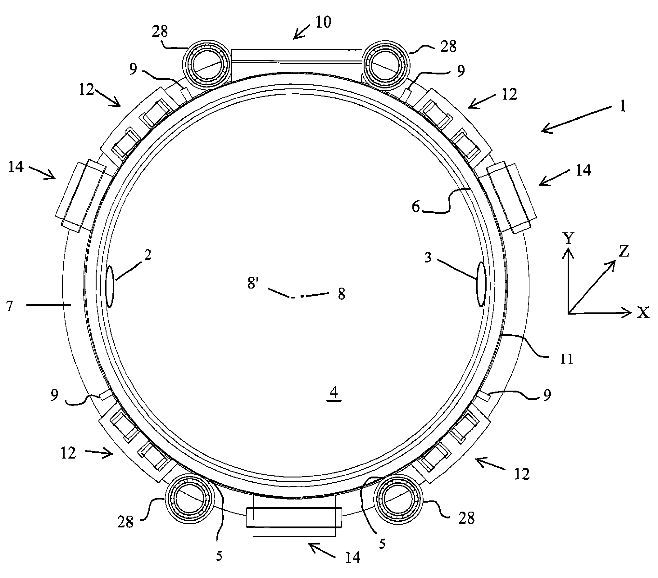
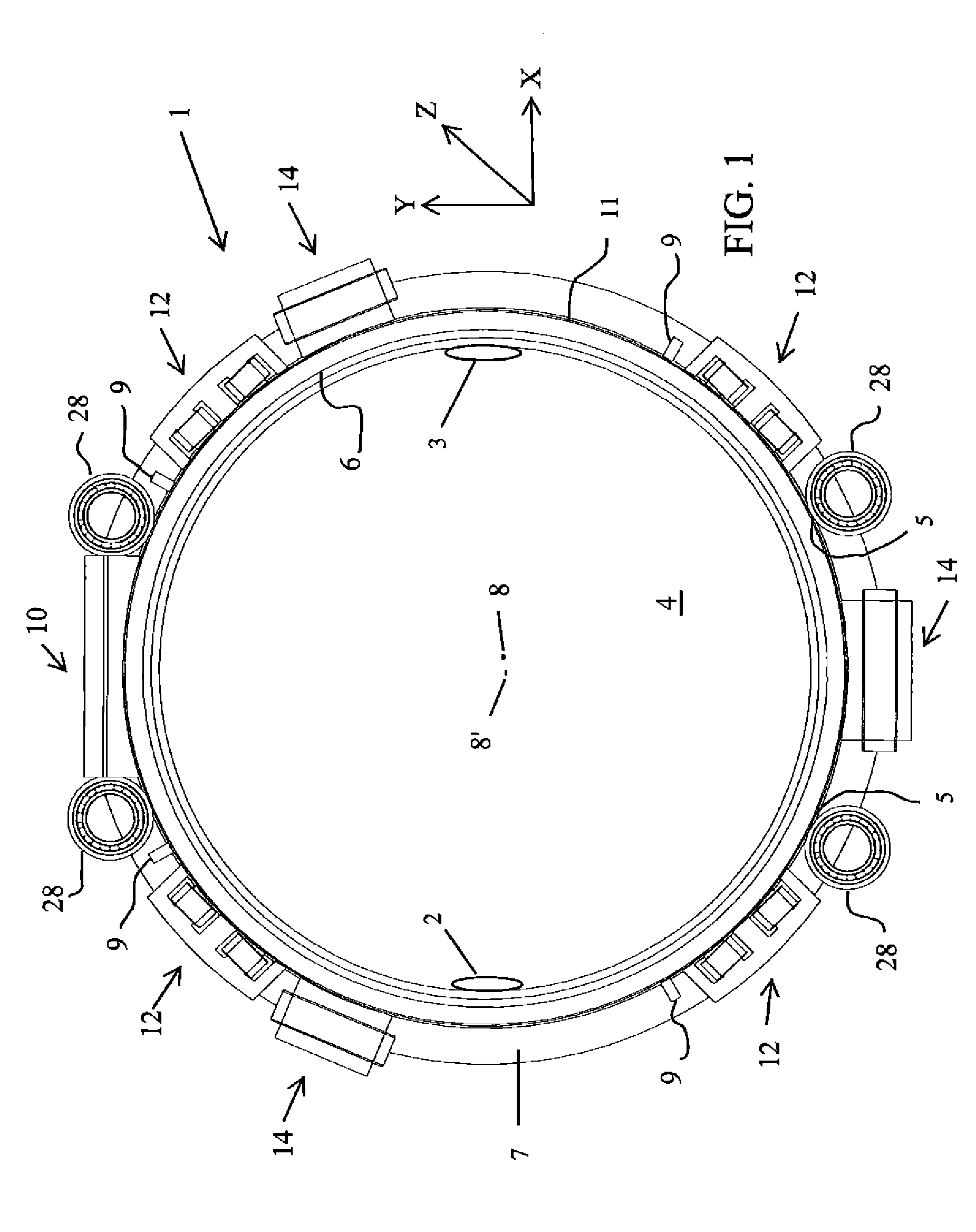
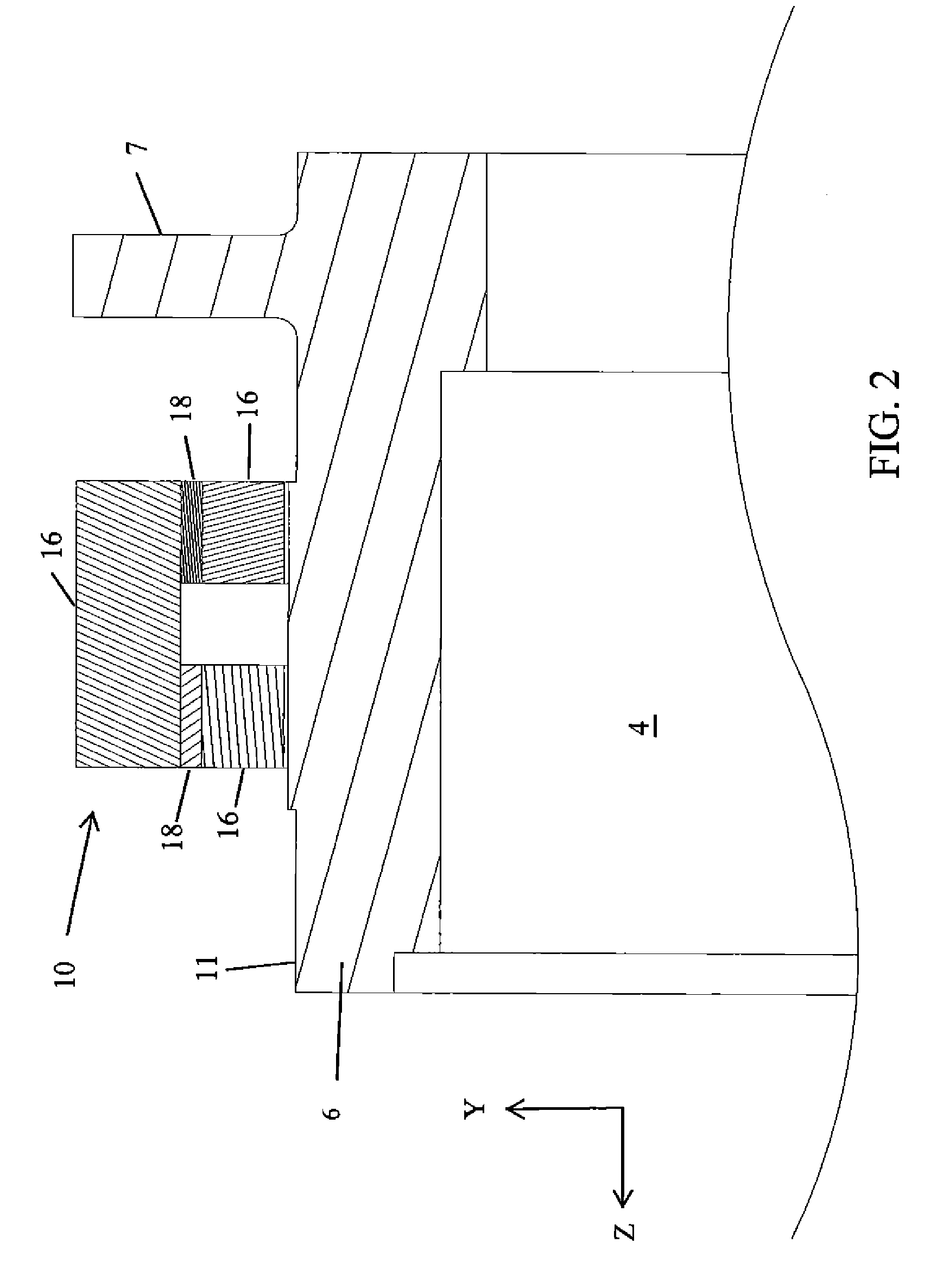
[0095]Each of the additional features and teachings disclosed below may be utilized separately or in conjunction with other features and teachings to provide improved bearings for annular rotors and / or bearing assemblies and / or diagnostic scanning systems, as well as methods for designing, constructing and using the same. Representative examples of the present invention, which examples utilize many of these additional features and teachings both separately and in combination, will now be described in further detail with reference to the attached drawings. This detailed description is merely intended to teach a person of skill in the art further details for practicing preferred aspects of the present teachings and is not intended to limit the scope of the invention. Therefore, combinations of features and steps disclosed in the following detail description may not be necessary to practice the invention in the broadest sense, and are instead taught merely to particularly describe repr...


PUM

PropertyMeasurementUnit
diameteraaaaaaaaaa
weightaaaaaaaaaa
distanceaaaaaaaaaa

Abstract

An apparatus includes an annular rotor that rotates about a rotational axis. A magnetic bearing system influences the position of the annular rotor in three-dimensional space and includes at least three actuators, wherein at least one actuator generates a force for lifting the annular rotor in a vertical direction, at least one actuator influences the position of the annular rotor in the radial direction of the annular rotor and at least assists in maintaining an annular gap between at least one non-magnetic bearing and the annular rotor during operation and at least one actuator influences the position of the annular rotor in an axial direction of the annular rotor. At least one radiation source may be fixedly mounted on the annular rotor.

Description

CROSS-REFERENCE[0001]This application claims priority to U.S. patent application No. 61 / 302,859 filed Feb. 9, 2010, the contents of which are fully incorporated herein by reference.TECHNICAL FIELD[0002]The present teachings generally relate to a diagnostic scanning apparatus, such as a computed tomography imaging system, having one or more magnetic bearings for rotatably supporting an annular rotor or gantry. The present teachings also relate more generally to arrangements for rotatably supporting an annular rotor, which rotates, e.g., in a substantially vertical or horizontal plane, using one or more magnetic bearings.BACKGROUND ART[0003]Known computed tomography (CT) imaging systems include a rotatable annular gantry or rotor having a gantry bore for receiving a patient or other object to be internally imaged. In typical CT applications, an x-ray source is mounted on the annular gantry and radiates a fan-shaped, wedge-shaped, or cone-shaped x-ray beam in the plane of gantry rotati...

Claims


Application Information

Patent Timeline
Patent Type & Authority Patents(United States)
IPC IPC(8): G01N23/00
CPCA61B6/035F16C29/005F16C29/0676F16C32/0465F16C32/0485F16C39/02F16C39/063F16C19/502F16C2300/14F16C2316/10A61B6/4423
Inventor HARRIS, TIMOTHY ANDREWSMITHANIK, JEFFREY RUSSELLTREMAINE, DAREN PAUL
Owner AB SKF
Why Eureka
Try Eureka