AI technical title is built by Patsnap AI team. It summarizes the technical point description of the patent document.
a technology of building walls and panels, applied in the field of building systems, can solve the problems of occupying interior space inside the building, requiring additional time and money to install, and limiting the effect of such insulation, and achieve the effect of sufficient strength
Active Publication Date: 2012-09-25
COMPOSITE PANEL SYST
View PDF128 Cites 17 Cited by
Summary
Abstract
Description
Claims
Application Information
AI Technical Summary
This helps you quickly interpret patents by identifying the three key elements:
Problems solved by technology
Method used
Benefits of technology
Benefits of technology
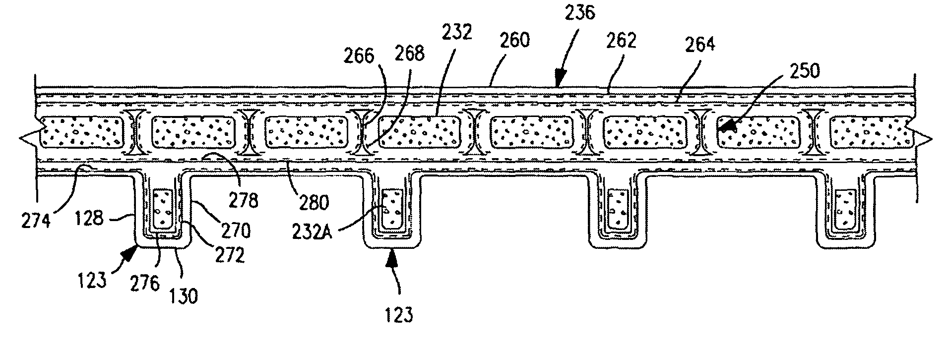
[0028]The structurally-reinforcing members may be integral with the inner and outer layers, whereby the reinforcing elements of the structurally-reinforcing members, which extend between the inner and outer layers, function in a capacity similar to the web of an I-beam, and associated portions of the inner and outer layers, function in capacities similar to the functioning of flanges of such I-beam. The overall I-beam effect provides, in an upstanding wall panel, or wall, both horizontal bending resistance and vertical compressive strength, sufficient to support both the vertical compressive loads, and the lateral side loads, for which building walls are designed, and can provide such sufficient levels of strength in cross-sections which are no greater than the cross-sections of steel reinforced concrete walls which are conventionally used in such applications, while avoiding the drawbacks of concrete.
Problems solved by technology
However, the affect of such insulation is limited because only relatively thin insulation materials are commonly used with underground concrete wall construction.
Such furring takes up interior space inside the building as well as costing additional time and money to install.
However, each such wall element must be custom-designed, adding to the cost; and relatively heavy-duty mechanical lifting equipment, e.g. the crane, must be brought to the construction site, also a cost item.
Getting foundation walls installed in a timely manner, to accommodate timely delivery of constructed homes and other buildings to buyers, is a significant issue in the construction business.
A substantial such problem is weather.
The weather in northern climates can be below freezing for several months of the year, which makes it difficult to get foundations installed.
In addition, installing quality concrete foundation walls requires skilled labor, as well as skilled subcontractors, including the subcontractors' skilled labor.
Although ICF walls do offer a relatively higher level of thermal insulation than a conventional uninsulated concrete wall, an ICF wall is typically more expensive than a plain concrete wall, and is more difficult to finish than a plain concrete wall, whether finishing the insulated interior of the wall or the insulated exterior of the wall.
However, wood foundations are not well received by the consuming public, as the public does not perceive quality in a building where wood is used in a below-grade application.
Method used
Image
Click on the blue label to locate the original text in one second.
Reading with bidirectional positioning of images and text.
Examples
example
[0156]Walls made according to this invention can readily satisfy the above deflection standard, given the following specification:
[0157]
Panel height108inches (2.7 m)Overall thickness6.88inches (17.5 cm)Thickness, main run wall section, incl layers3.25inches (8.3 cm)34 and 36Stud depth3.63inches (9.2 cm)Thickness of layers 34, 360.09inch (2.3 mm)Thickness of stud side walls and end panels0.09inch (2.3 mm)Glass specification as described hereinafter with respect to FIG. 5A.
[0158]Applicants have surprisingly discovered / observed that, when upright walls and wall panels made according to the above specification are subjected to top / compressive loads which are evenly distributed from outer layer 36 of the main run wall section to end panels 130 of the studs, such walls and wall panels deflect outwardly of the building, toward outer layer 36, 236, namely toward the soil back fill. Thus, the natural horizontal / lateral soil loading applied by the backfilled soil, is at least in part countere...
PUM
Property
Measurement
Unit
thick
aaaaa
aaaaa
thick
aaaaa
aaaaa
height
aaaaa
aaaaa
Abstract
Methods of fabricating wall panels by generally continuously pultruding a wall panel profile comprising inner and outer layers, and spaced reinforcing webs and / or foam extending between the inner and outer layers, optionally studs extending inwardly from the inner layer, away from the outer layer. The so-continuously pultruded wall panel optionally has male and a female edges. The wall panel is periodically cut for wall panel height, thereby creating an ongoing stream of cut wall panels. The panels are advanced through a corner index station, and indexed at right angles while maintaining orientation of the panels. The wall panels leave the indexing station edge-to-edge. Resin is applied to facing edges of adjacent wall panels. Adjacent wall panels are joined to each other at the facing edges, to make a generally continuous wall panel. The so-joined wall panel is cut to desired lengths. The resulting wall panel can provide tough, water-proof, otherwise weather-proof, building systems and buildings, without structural use of concrete except in floor slabs.
Description
CROSS REFERENCE TO RELATED APPLICATIONS[0001]This application is a Non-Provisional of 61 / 008,379, filed Dec. 19, 2007, this application is a Continuation-in-Part of application Ser. No. 11 / 901,174 filed Sep. 13, 2007, this application is a Continuation-in-Part of application Ser. No. 11 / 901,057, filed Sep. 13, 2007, this application is a Continuation-in-Part of application Ser. No. 11 / 900,987, filed Sep. 13, 2007, this application is a Continuation-in-Part of application Ser. No. 11 / 900,998, filed Sep. 13, 2007, this application is a Continuation-in-Part of application Ser. No. 11 / 901,059, filed Sep. 13, 2007, this application is a Continuation-in-Part of application Ser. No. 11 / 901,173, filed Sep. 13, 2007, this application is a Continuation-in-Part of application Ser. No. 11 / 901,175, filed Sep. 13, 2007, this application is a Non-Provisional of application Ser. No. 60 / 872,929, filed Dec. 4, 2006, this application is a Non-Provisional of 60 / 876,403, filed Dec. 21, 2006, this applic...
Claims
Application Information
Patent Timeline
Application Date:The date an application was filed.
Publication Date:The date a patent or application was officially published.
First Publication Date:The earliest publication date of a patent with the same application number.
Issue Date:Publication date of the patent grant document.
PCT Entry Date:The Entry date of PCT National Phase.
Estimated Expiry Date:The statutory expiry date of a patent right according to the Patent Law, and it is the longest term of protection that the patent right can achieve without the termination of the patent right due to other reasons(Term extension factor has been taken into account ).
Invalid Date:Actual expiry date is based on effective date or publication date of legal transaction data of invalid patent.

