Instrumentation for recording and replicating orthopaedic implant orientation

a technology for orthopaedic implants and instruments, which is applied in the field of orthopaedic implants, can solve the problems of inability of surgeons to system, and patient, and achieve the effect of accurately duplicate the orientation or configuration of a trial, and easy preparation of the final implan

Active Publication Date: 2012-09-25
DEPUY SYNTHES PROD INC
View PDF79 Cites 13 Cited by
  • Summary
  • Abstract
  • Description
  • Claims
  • Application Information

AI Technical Summary

Benefits of technology

[0012]These and other needs are met by the present inventive recording and replication instrumentation that is capable of replicating the orientation of a dialable component of an implant relative to the bone engaging component of the implant. For instance, the present invention has particular value in the preparation of a final humeral implant having a stem configured for fixation within the humerus bone and a spherical head that is “dialably” mounted to the stem—i.e., is adjustably mounted so the three-dimensional angulation of the head can be adjusted as necessary for the particular patient anatomy.
[0023]It is one object of the invention to provide a system and method for readily and easily preparing a final implant that accurately duplicates the orientation or configuration of a trial implant that has been used to determine the proper implant configuration. Another object resides in features of the invention that ensure virtually identical replication of the position of a dialable component of an orthopedic implant.
[0024]One benefit of the invention is that the inventive system and method permits use of standard trial and final implants. Another benefit is that the final implant can be prepared apart from the patient without sacrificing an optimal anatomical fit for the implant, which can be especially valuable where locking tapers are used.

Problems solved by technology

Even with respect to these two divergent manners of surgical strategy, a common problem in shoulder surgery is matching the humeral resection angle across the articular margin to the predetermined angle designed into the prosthesis.
This strategy does not allow the surgeon to intraoperatively match the implant to the patient's biomechanics after the prosthesis has been trialed, much less implanted.
This system, however, has two primary weaknesses.
First, the use of modular blocks obviously forces the design to only allow angular adjustments in finite increments.
Second, the need to adjust the angle through modular blocks forces the surgeon to remove the stem, change out a component, and reset the stem.
The locking mechanism, however, is sub-optimal since it requires the turning of a locking screw that has its head facing lateral and inferior, for which there is no access once the stem has been cemented.
Lastly, the protrusion on the humeral stem even when the humeral head is not in place limits the surgeon's access to the glenoid in preparation for a glenoid replacement.
One such prosthesis that has attempted to provide this design feature provides a complicated and cumbersome jig to permit replication of the head angular position between the trial prosthesis and the final implant.
One problem with this jig is that the head position is taken directly from the long axis of the humeral stem.
This means that the system has a large number of components to handle, and the position cannot be adjusted with the stem in vivo.
Another problem is that the jig itself is a quite complicated table-top device.

Method used


Image

  • Instrumentation for recording and replicating orthopaedic implant orientation
  • Instrumentation for recording and replicating orthopaedic implant orientation
  • Instrumentation for recording and replicating orthopaedic implant orientation

Examples


Embodiment Construction

[0037]While the invention is susceptible to various modifications and alternative forms, specific embodiments thereof have been shown by way of example in the drawings and will herein be described in detail. It should be understood, however, that there is no intent to limit the invention to the particular forms disclosed, but on the contrary, the intention is to cover all modifications, equivalents, and alternatives falling within the spirit and scope of the invention.

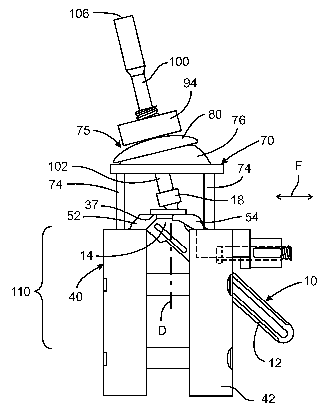
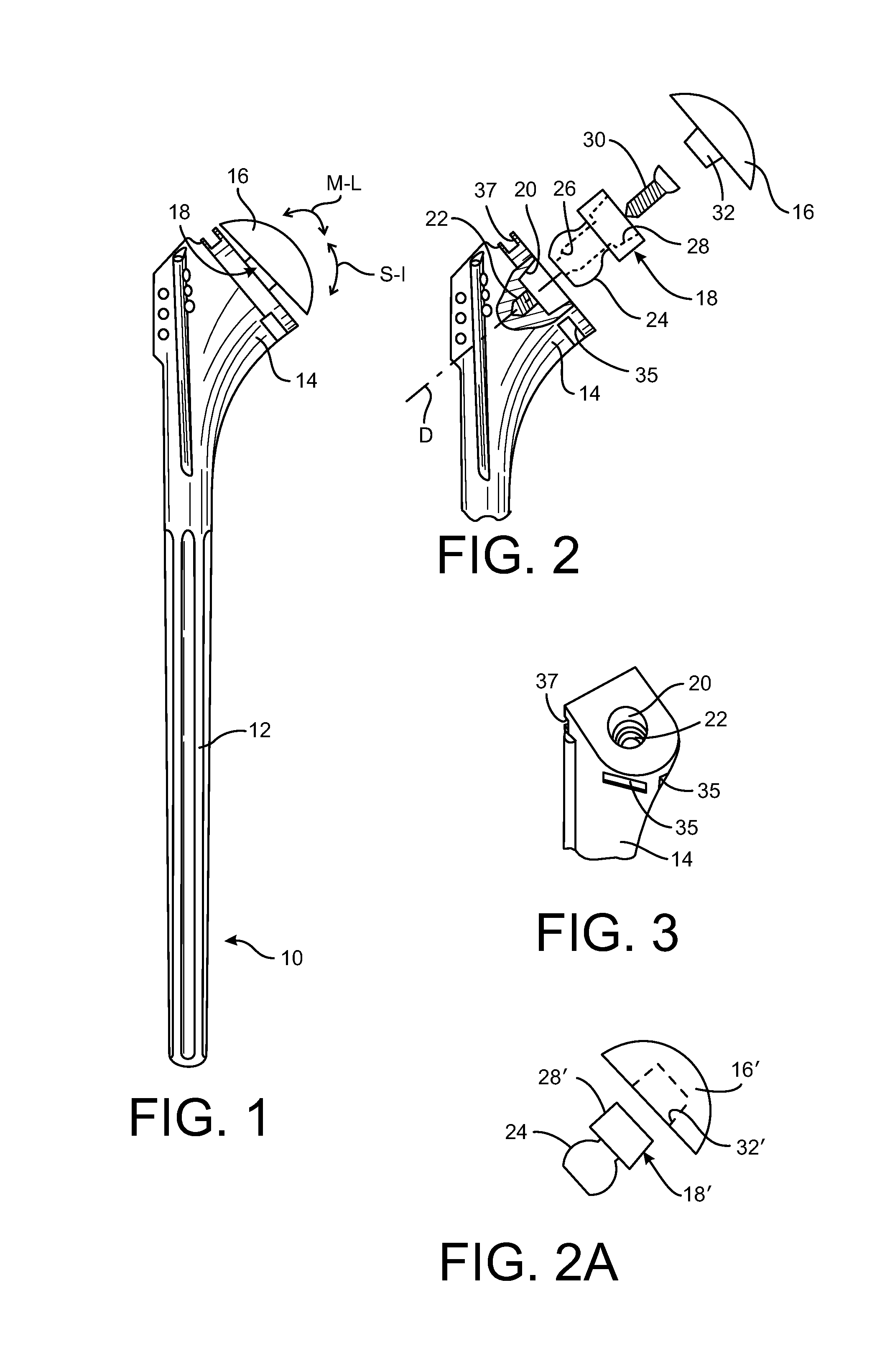
[0038]For purposes of illustration, the preferred embodiment of the invention is described in connection with a shoulder prosthesis, and particularly the humeral component of the prosthesis. However, the inventive concepts disclosed herein can be used at other joints or bone interfaces of the body. The common feature among these alternative uses of the invention is that they include components that can assume a range of angular orientations relative to each other—angular orientations that must be duplicated from a tria...


PUM


Abstract

An instrument for recording and replicating the spatial orientation of a dialable component of an implant relative to a bone engaging component of the implant includes a base assembly for supporting the bone engaging component and a fixture supported on the base assembly for supporting an alignment tool. The alignment tool is configured to engage a portion of the dialable component when the implant is supported by the base assembly. The fixture includes a locking assembly for locking the spatial position of the alignment tool relative to a pre-determined datum on a trial implant. The same instrument can be used to support a final implant and to replicate the spatial position of the alignment tool relative to the same datum on the final implant. The alignment tool can then be used to align the dialable component of the implant. The alignment tool can also constitute an impacting tool so that it can be used to impact the dialable component into locking engagement with the implant using the same instrument.

Description

BACKGROUND OF THE INVENTION[0001]1. Field of the Invention[0002]The present invention relates to prosthetic devices particularly shoulder prostheses and, more particularly, to a method and apparatus for replication of angular position of a humeral head of a shoulder prosthesis.[0003]2. Background Information[0004]The state of the prosthetic shoulder market has progressed such that a surgeon generally approaches shoulder replacement surgery according to one of two strategies. One strategy is to perform the shoulder replacement surgery in accordance with a manufacturer's shoulder prosthesis or shoulder prosthesis product line. Particularly, a surgeon is provided with instrumentation and technique guidelines for the particular shoulder prosthesis or prosthesis line. The guidelines and / or instrumentation direct or dictate the angle of humeral head resection for the implant (prosthesis). This angle is in relation to the humeral intramedullary (IM) canal and is designed to match an optimu...

Claims


Application Information

Patent Timeline
Patent Type & Authority Patents(United States)
IPC IPC(8): A61B17/58A61B17/60A61F2/00A61B17/88A61F2/02A61F2/40A61F2/46
CPCA61F2/4014A61F2/4657A61F2/4059A61F2/4684A61F2002/30332A61F2002/30378A61F2250/0006A61F2002/30538A61F2002/4037A61F2002/4044A61F2002/4668A61F2220/0025A61F2220/0033A61F2002/30507
Inventor KLOTZ, CONRADDEFFENBAUGH, DARENWILKINSON, TRENTFRAZEE, EDMUND
Owner DEPUY SYNTHES PROD INC
Why Eureka
Try Eureka