

Driving methods for bistable displays
- Summary
- Abstract
- Description
- Claims
- Application Information
AI Technical Summary
Benefits of technology
Problems solved by technology
Method used
Image

Examples
Embodiment Construction
[0030]A detailed description of the driving methods is provided below with figures that illustrate by way of examples. While the invention is described in connection with these examples, it should be understood that the invention is not limited to any of the exemplified methods. On the contrary, the scope of the invention is limited only by the appended claims and the invention encompasses numerous alternatives, modifications and equivalents. For the purpose of example, numerous specific details are set forth in the following description in order to provide a thorough understanding of the present invention. The present invention may be practiced according to the claims without some or all of these specific details. For the purpose of clarity, technical material that is known in the technical fields related to the invention has not been described in detail so that the present invention is not unnecessarily obscured.
1.0 Context for Embodiments
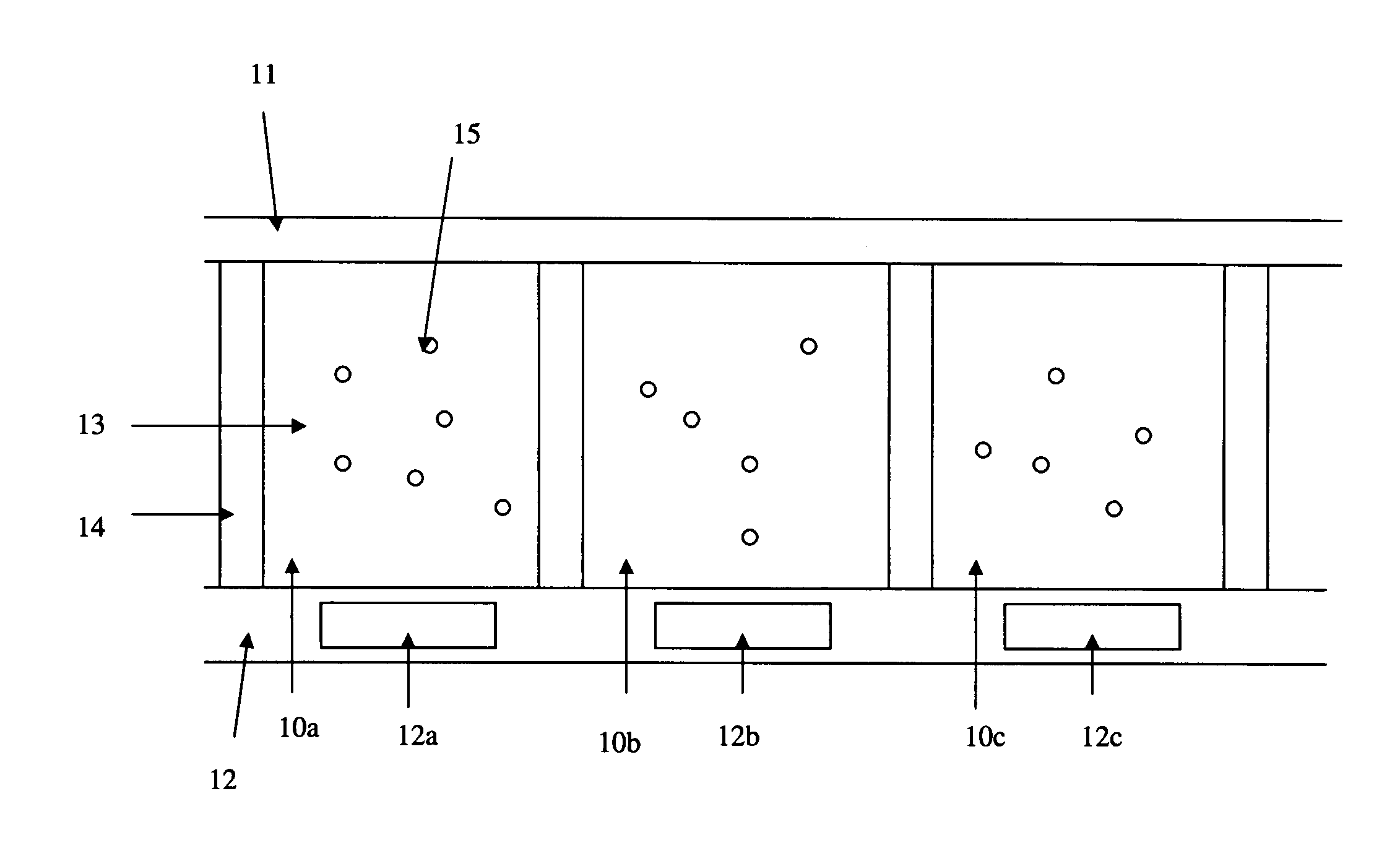
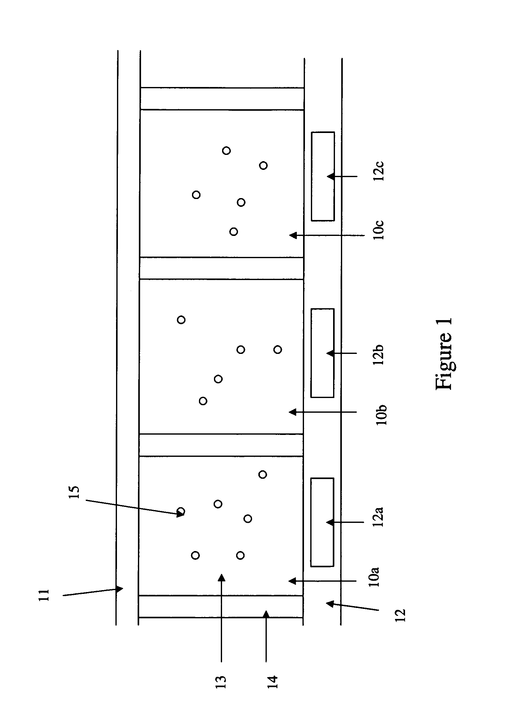
[0031]1.1 Electrophoretic Display Structur...
PUM
 Abstract
Description
Claims
Application Information