System for using constricted convection with closed loop plenum as the convection plate

a technology of closed loop plenum and convection plate, which is applied in the direction of cooling/ventilation/heating modification, instruments, electrical equipment, etc., can solve the problems of insufficient cooling in many climates, and achieve the effect of large fluctuation in temperature and greater cooling capacity

Active Publication Date: 2012-09-25
MFG RESOURCES INT INC
View PDF64 Cites 64 Cited by
  • Summary
  • Abstract
  • Description
  • Claims
  • Application Information

AI Technical Summary

Problems solved by technology

By itself, this is not adequate in many climates, especially when radiative heat transfer from the sun through a display window becomes a major factor.

Method used


Image

  • System for using constricted convection with closed loop plenum as the convection plate
  • System for using constricted convection with closed loop plenum as the convection plate
  • System for using constricted convection with closed loop plenum as the convection plate

Examples


Embodiment Construction

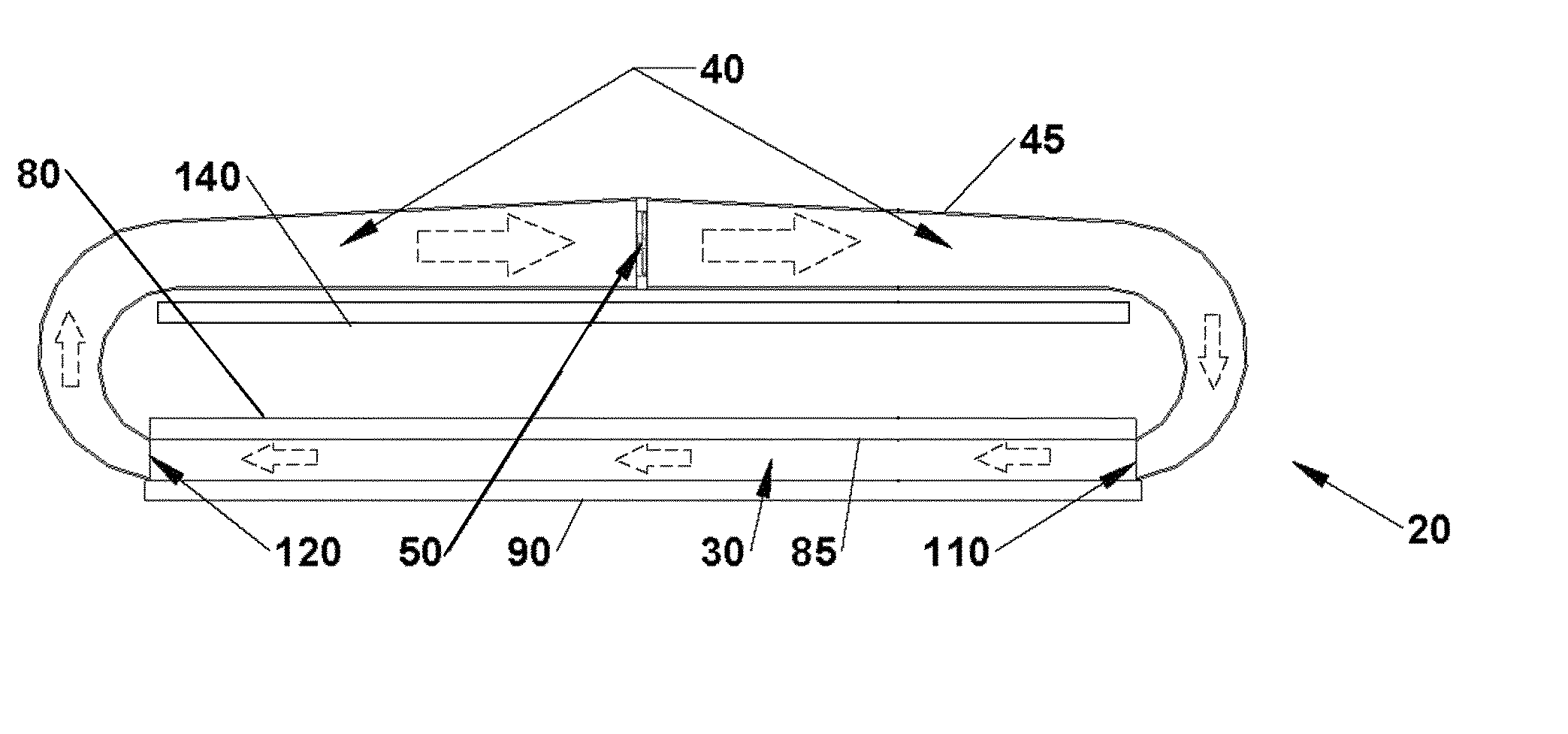
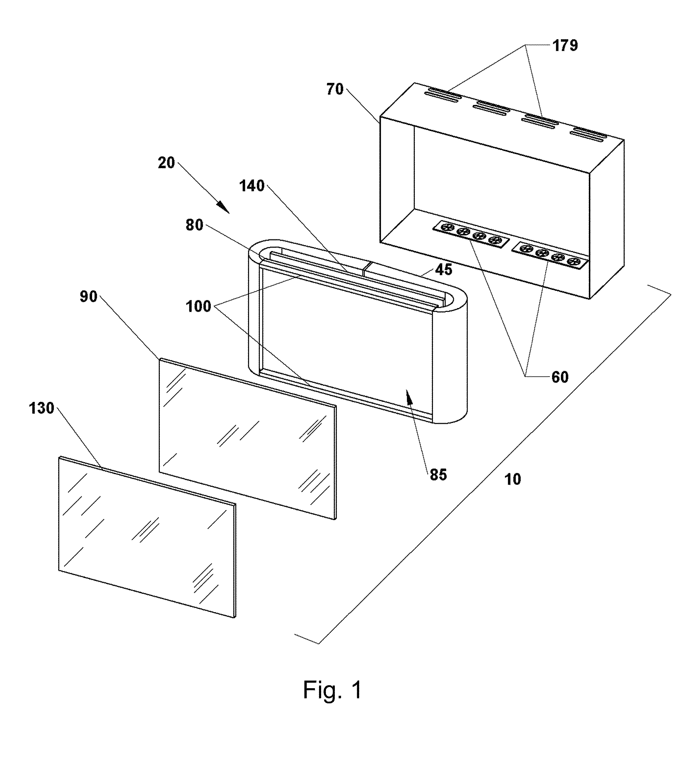
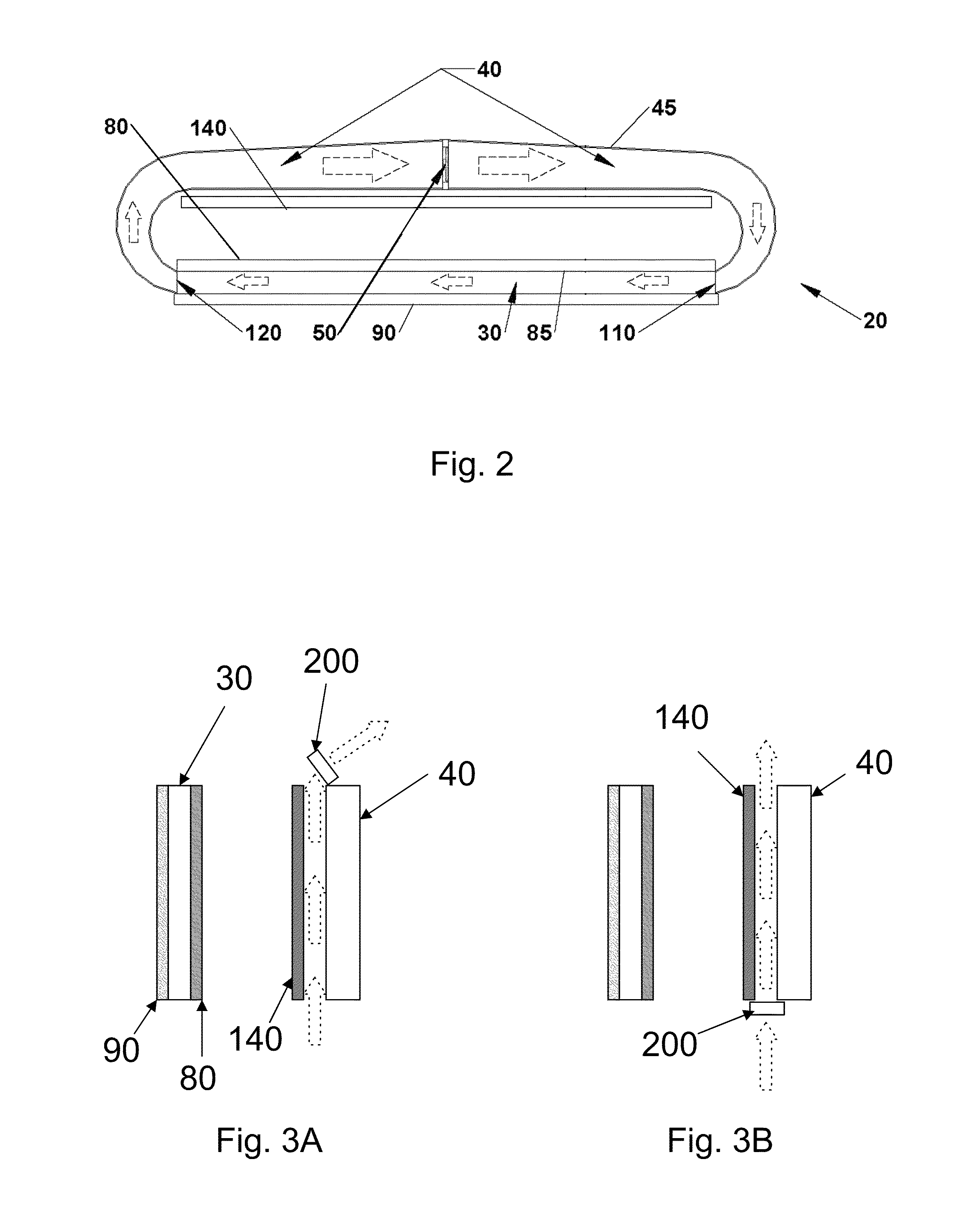
[0005]A large fluctuation in temperature is common in the devices of the past. Such temperature fluctuation adversely affects the electronic components in these devices. Whereas the systems of the past attempted to remove heat only through the non-display sides and rear components of the enclosure surrounding the electronic display components, a preferred embodiment causes convective heat transfer from the face of the display as well. By the aspects described below, exemplary embodiments have made consistent cooling possible for electronic displays having screens of sizes greater than or equal to twelve inches. For example, cooling of a 55 inch screen can be achieved, even in extremely hot climates. Greater cooling capabilities are provided by the device and method described and shown in more detail below.

[0006]An exemplary embodiment relates to an isolated gas cooling system and a method for cooling an electronic display. An exemplary embodiment includes an isolated gas cooling cha...


PUM

PropertyMeasurementUnit
poweraaaaaaaaaa
sizesaaaaaaaaaa
distanceaaaaaaaaaa

Abstract

A cooling system and a method for cooling an electronic display. A preferred embodiment utilizes a closed loop cooling system in a constricted convection cooling setup to remove heat from the backlight of a display assembly. Cooling air can be pulled or pushed through a gap between the display (or backlight) and a rear cooling chamber. The resulting warm air can then be exhausted out of the display housing. The cooling air may be air conditioned or may be exposed to a thermoelectric device. A thermostat may be used so that cooling fans are only energized when the temperature reaches a predetermined point.

Description

CROSS-REFERENCE TO RELATED APPLICATIONS[0001]This application is a non-provisional of U.S. Application No. 61 / 115,333 filed Nov. 17, 2008 and is hereby incorporated by reference as if fully cited herein. This application is a continuation in part of U.S. application Ser. No. 12 / 411,925 filed Mar. 26, 2009, which is a non-provisional application of U.S. provisional application No. 61 / 039,454 filed Mar. 26, 2008 each of which are hereby incorporated by reference as if fully cited herein. This application is a continuation-in-part of U.S. application Ser. No. 12 / 556,029 filed Sep. 9, 2009, which is a non-provisional application of U.S. provisional application No. 61 / 095,615 filed Sep. 9, 2008 each of which are hereby incorporated by reference as if fully cited herein. This application is a continuation-in-part of U.S. application Ser. No. 12 / 234,307 filed Sep. 19, 2008, which is a non-provisional application of U.S. Application No. 61 / 033,064 filed Mar. 3, 2008, each of which are hereb...

Claims


Application Information

Patent Timeline
Patent Type & Authority Patents(United States)
IPC IPC(8): G02F1/1333
CPCH05K7/20972H05K7/20136G02F1/133385H05K7/20954G02F1/133308G02F1/133603G02F1/133615G02F2201/36H05K7/20127H05K7/20145H05K7/20163H05K7/202H05K7/20209
Inventor DUNN, WILLIAM
Owner MFG RESOURCES INT INC
Why Eureka
Try Eureka