Underwater network having buoyancy compensation and anchoring systems

a technology of buoyancy compensation and anchoring system, which is applied in the direction of sonic/ultrasonic/infrasonic transmission, electrical apparatus, transmission, etc., can solve the problems of difficulty in transporting each network node, moving the nodes to an undesired location without the knowledge of the network operator, and achieving neutral buoyancy, the effect of facilitating the transport of nodes and more hydrodynamics

Inactive Publication Date: 2012-09-25
THE UNITED STATES OF AMERICA AS REPRESENTED BY THE SECRETARY OF THE NAVY
View PDF2 Cites 6 Cited by
  • Summary
  • Abstract
  • Description
  • Claims
  • Application Information

AI Technical Summary

Benefits of technology

[0008]The housing can further be formed with at least two flood ports, and the nodes according to several embodiments can further include at least two plugs, with each plug corresponding to a respective fill port. A lanyard or lanyards can interconnect the flukes and the plugs. During transport, the flukes surround the transd

Problems solved by technology

There can often be inherent difficulties in establishing underwater networks.
The first difficulty can be transporting each network node to its desired underwater location.
If the nodes are negatively buoyant, this can result in a diver attempting to manually maneuver a node that might weigh over a hundred pounds, which is obvi

Method used


Image

  • Underwater network having buoyancy compensation and anchoring systems
  • Underwater network having buoyancy compensation and anchoring systems
  • Underwater network having buoyancy compensation and anchoring systems

Examples


Embodiment Construction

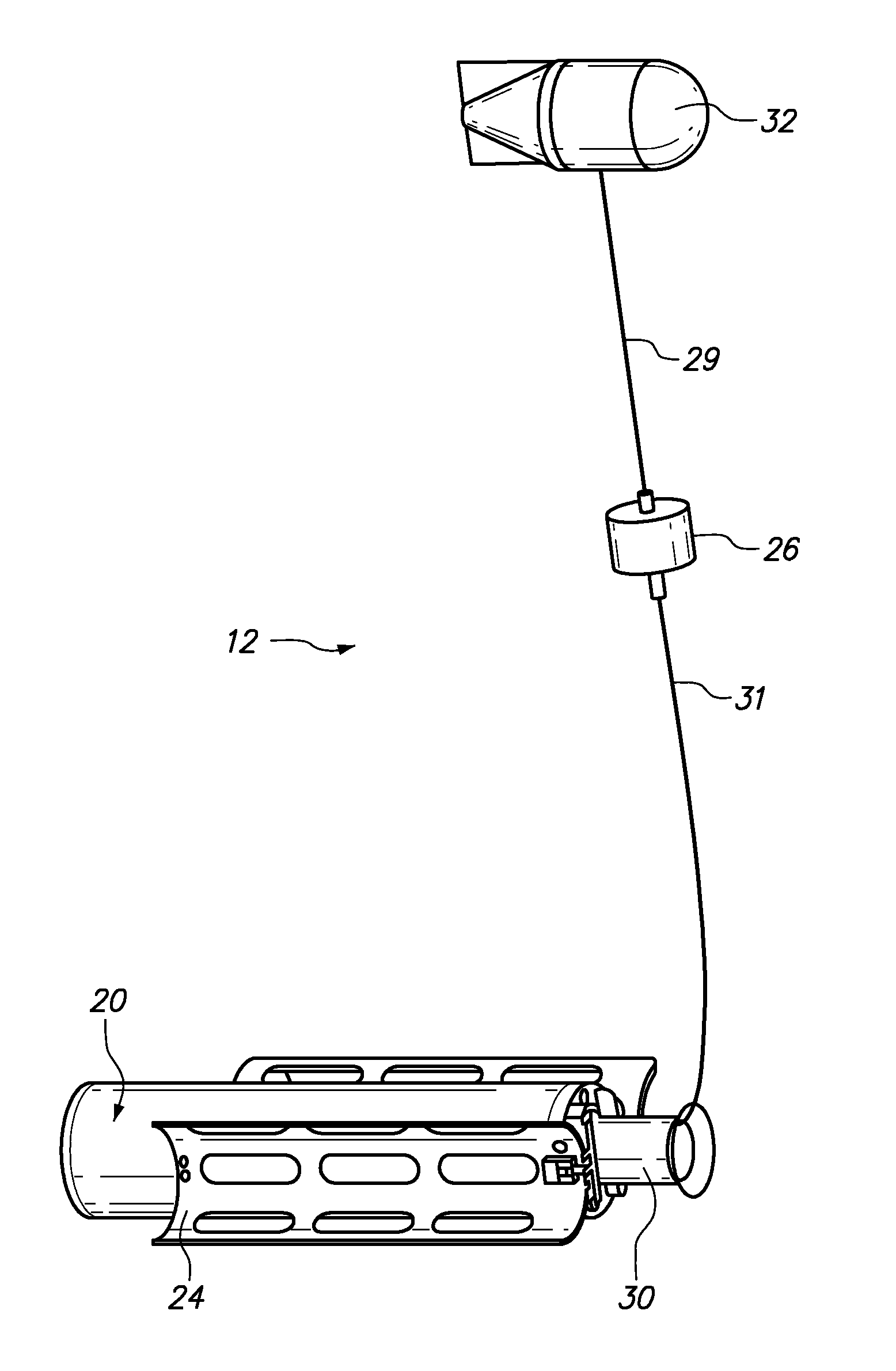
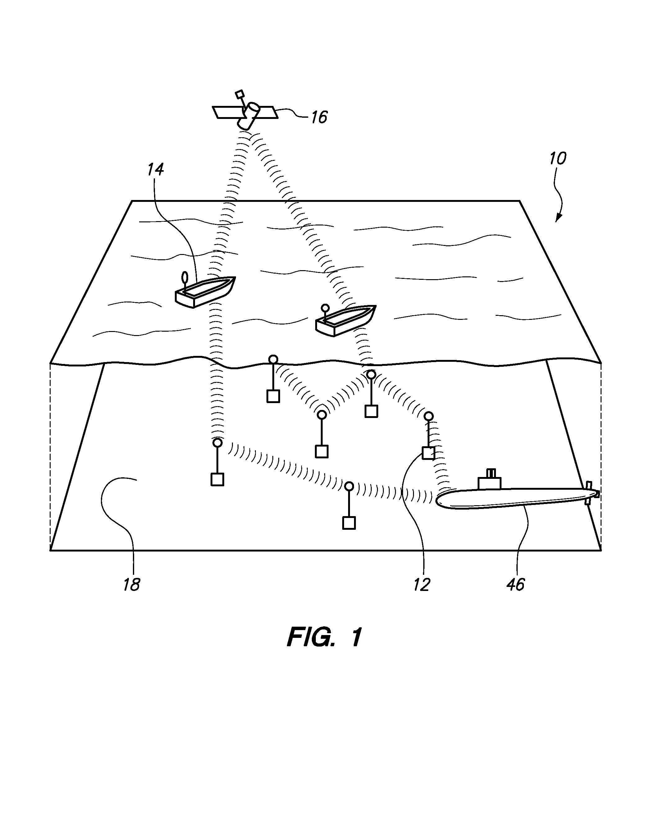
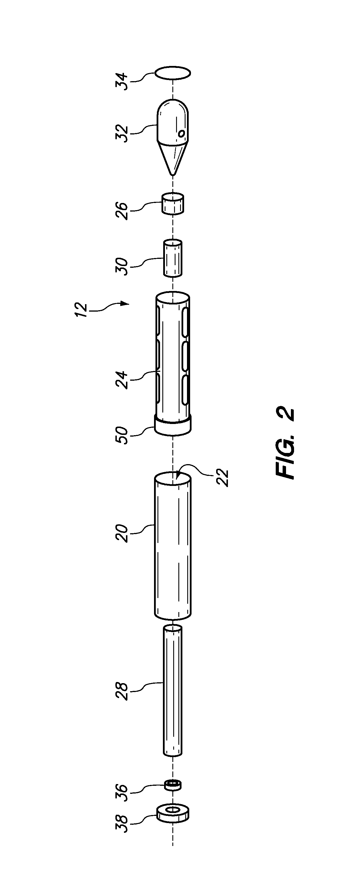
[0019]Referring now to the Figures, the underwater wireless data transfer network according to several embodiments of the present invention can be shown and can be generally designated by reference character 10. In brief overview, and as shown in FIG. 1, the system 10 includes a plurality of underwater network nodes 12 that can be positioned and anchored on the floor 18 of an ocean or harbor. The nodes 12 can communicate with each other, with underwater assets such as submarine 46 and with surface assets 14. The network 10 can also be placed in communication with airborne assets 16 to establish an expanded communications network. But to do this, the underwater nodes must be efficiently and effectively maneuvered into position on the floor 18 of the ocean / harbor. The structure of the nodes 12, and the manner in which the nodes 12 can be maneuvered into position and fixed in place within the network 10 during deployment, are described in more detail below.

[0020]Referring now to FIGS. ...


PUM


Abstract

An underwater wireless network can include plurality of nodes, each node having a cylindrical housing, a repeater, a transducer and a buoy. The housing defines a void and encloses the repeater. The transducer can be tethered to the housing and a buoy can be tethered to said transducer. Each node also includes at least two hemi-cylindrical flukes that can be pivotably attached to the housing. The housing can further be formed with at least two flood ports, and corresponding plugs are inserted into a respective fill port. Lanyards interconnect each flukes with a respective plug. During transport, the flukes can surround the transducer and the void is empty, which renders the node neutrally buoyant for ease of transport. For deployment, the flukes are pivoted away from each other to tighten the lanyards, which pull the plugs out of the flood ports, to further flood the void and deploy the node.

Description

FEDERALLY-SPONSORED RESEARCH AND DEVELOPMENT[0001]This invention (Navy Case No. 099708) is assigned to the United States Government and is available for licensing for commercial purposes. Licensing and technical inquires may be directed to the Office of Research and Technical Applications, Space and Naval Warfare Systems Center, Pacific, Code 72120, San Diego, Calif. 92152; voice (619) 553-2778; email T2@spawar.navy.mil.FIELD OF THE INVENTION[0002]The present invention pertains generally to systems and methods for providing an underwater wireless data network. More specifically, the present invention pertains to systems that provide for neutral buoyancy of underwater network nodes for easy movement during underwater transport, while also providing for ballast, anchoring and anti-roll effects after deployment of the nodes.BACKGROUND OF THE INVENTION[0003]It is sometimes desired to provide a capability to extend wireless networking capabilities from the terrestrial to the underwater d...

Claims


Application Information

Patent Timeline
IPC IPC(8): H04B13/02H04B7/14
CPCH04B11/00H04B13/02
Inventor MARN, WILLIAM H.PENNEY, JAMES BENHAMME, LONNIE ALLENFLETCHER, CHRISTOPHER LAWSONCREBER, ROBERT KEVINBUESCHER, JAMES GABRIEL
Owner THE UNITED STATES OF AMERICA AS REPRESENTED BY THE SECRETARY OF THE NAVY
Why Eureka
Try Eureka