Hydrodynamic, down-hole anchor

a technology of anchors and hydraulics, applied in the field of wells, can solve the problems of limiting gas production and unoptimized equipment now in use, and achieve the effects of reducing drag area and drag shape factors, improving gas production, and facilitating their admittan

Active Publication Date: 2007-08-14
TECH TAC
View PDF18 Cites 67 Cited by
  • Summary
  • Abstract
  • Description
  • Claims
  • Application Information

AI Technical Summary

Benefits of technology

[0009]An anchor may be applied to wells having flows in an annulus formed between the exterior of the tubing and the interior of the well bore. For example, in certain embodiments, an anchor may be applied to a coal bed methane well. An anchor in accordance with the present invention may provide the structure necessary to accomplish the anchoring function without overly blocking or interfering with flow in this annulus. For example, in selected embodiments, anchors in accordance with the present invention may be generated in a comparatively smaller diameter to leave a greater space between the anchor and the well bore. Oversized slips may be used to accomplish the greater throw (radial extension) necessary to reach and engage (grip) the well bore. If desired, oversized slips may be chamfered or otherwise shaped to facilitate their admittance within the anchor housing during assembly. This increase in space or clearance between the anchor and the well bore may reduce drag area and drag shape factors to improve gas production from coal bed methane wells to levels unobtainable with conventional anchors.
[0010]In selected embodiment, fairings or flow directors may be applied to an anchor. The fairings may make the anchor more hydrodynamic and less disruptive to the flow of water, gas, and debris past the anchor. In certain embodiments, fairings may be placed on only one end of a well anchor. The end selected for the fairing may be the leading or trailing end with respect to flow in the annulus between the well bore and the tubing being. In an alternative embodiment, a fairing may be applied to both ends of the well anchor. Gas and water may flow up past an anchor or down past an anchor to exit the well. They may travel up the bore, to a pump, or the like. With a fairing on both ends of anchor, the flow characteristics of the gas and water can be the same no matter which direction the gas and water are traveling (i.e. up or down within the well bore). This may be useful in situations where it is difficult to determine before installation which direction the flow in the annulus with be traveling at any given depth.
[0011]Increased spacing between an anchor housing and a well casing may provide several advantages. As mentioned, the spacing may permit fluids to pass by more easily. Also, the increased spacing and resulting flow appear to limit resultant corrosion. Moreover, the spacing may facilitate removal of an anchor that becomes jammed, seized, or otherwise inoperatively locked in a well bore. The smaller diameter of an anchor housing may allow a tool (e.g. a coring drill bit) to free a jammed anchor by simply cutting through the slips extend radially outward therefrom. Thus, the tool need not cut through the entire length of an anchor housing as may be the case with anchors of a larger, conventional diameter. By limiting the amount of material that must be drilled out, removed, or cut, significant time savings may be achieved.

Problems solved by technology

However, some of the equipment now in use is not optimal for the unique requirements of coal bed methane collection.
When applied to a coal bed methane wells, typical anchors may limit gas production.

Method used


Image

  • Hydrodynamic, down-hole anchor
  • Hydrodynamic, down-hole anchor
  • Hydrodynamic, down-hole anchor

Examples


Embodiment Construction

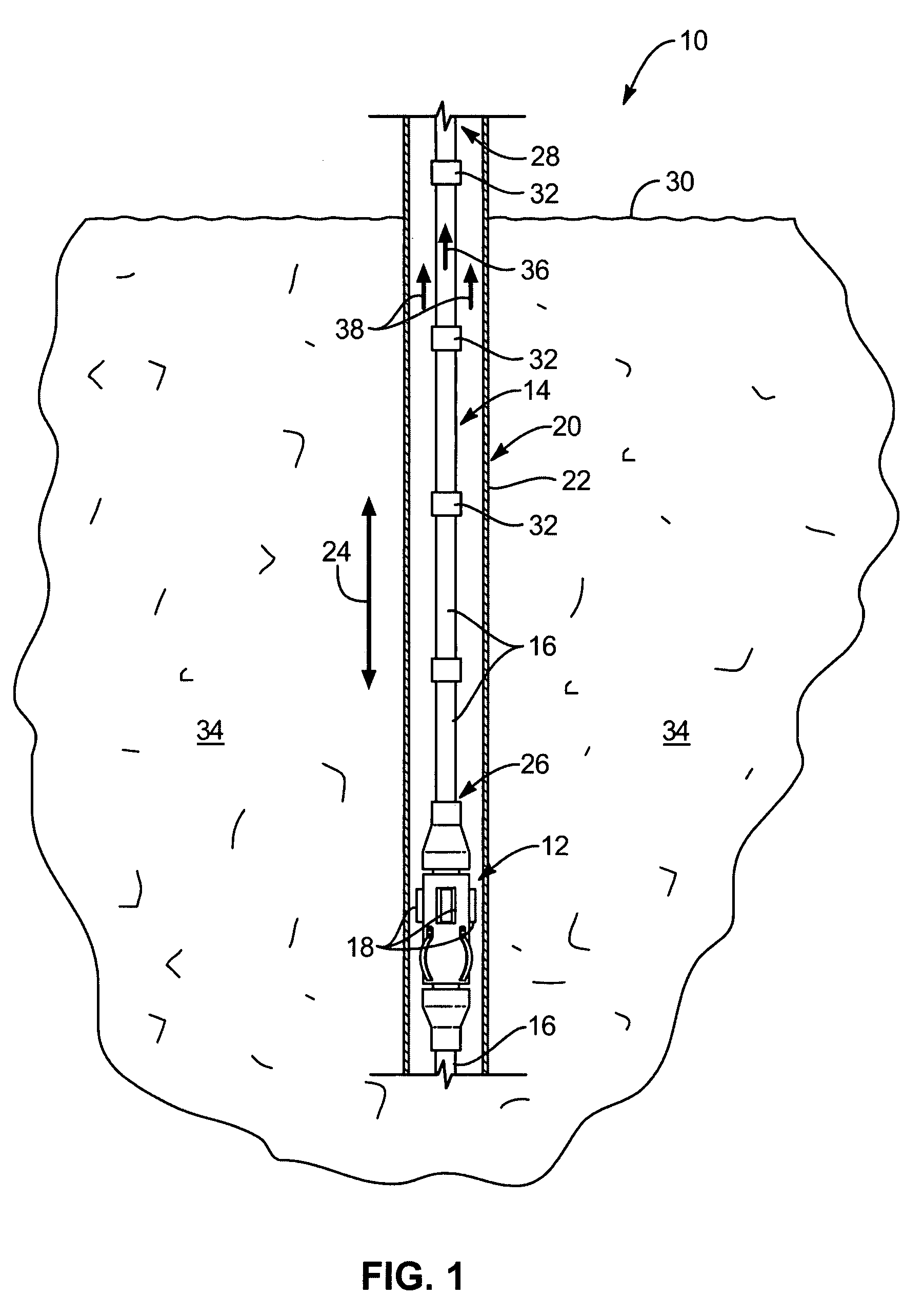
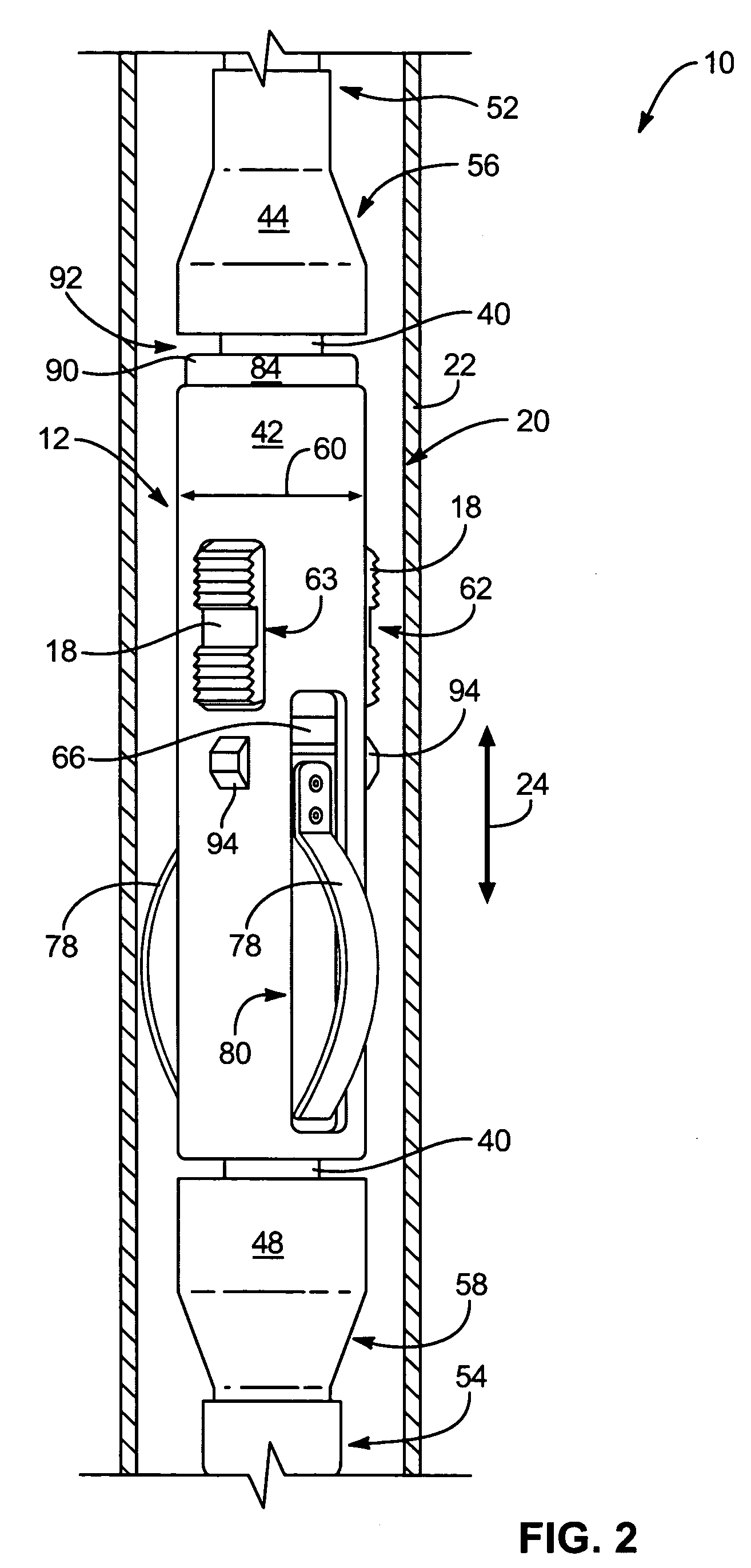
[0042]It will be readily understood that the components of the present invention, as generally described and illustrated in the Figures herein, could be arranged and designed in a wide variety of different configurations. Thus, the following more detailed description of the embodiments of the system and method of the present invention, as represented in FIGS. 1 through 29, is not intended to limit the scope of the invention, as claimed, but is merely representative of various embodiments of the invention. The illustrated embodiments of the invention will be best understood by reference to the drawings, wherein like parts are designated by like numerals throughout.

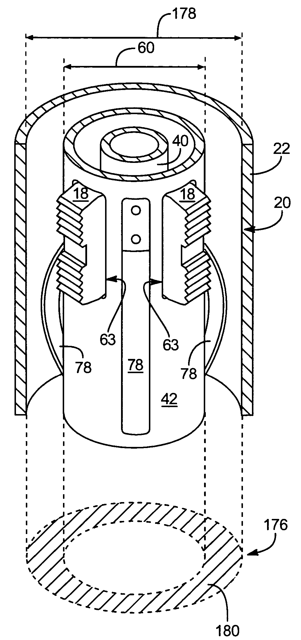
[0043]Referring to FIG. 1, in various types of wells 10, it may be desirable to employ an anchor 12 to secure tubing 14 within the well 10. In general, an anchor 12 may be connected in series with various sections 16 of tubing 14. After being lowered within a well bore 20 to a selected depth, the tubing 14 may rotated, caus...


PUM


Abstract

A method of removably anchoring well tubing in a well bore may include selecting a well having a bore diameter and an anchor positioned therein. The anchor may have a housing defining an anchor diameter and extension members extending therefrom toward the bore diameter. The bore diameter and anchor diameter may be spaced apart a distance defining an annulus therebetween and extending along the well. A tool sized to cut substantially exclusively within the annulus may be selected. The tool may be positioned within the annulus, rotated, and advanced to drive past the housing to remove the extension members between the housing and the bore diameter to free the anchor.

Description

RELATED APPLICATIONS[0001]This application claims the priority benefit of co-pending U.S. Provisional Patent Application Ser. No. 60 / 561,699, filed on Apr. 13, 2004 for SLIP WELL ANCHOR.BACKGROUND[0002]1. The Field of the Invention[0003]This invention relates to wells and, more particularly, to novel systems and methods for anchoring tubing within a well bore.[0004]2. The Background Art[0005]The presence of methane (CH4, a principal ingredient of natural gas) in underground coal seams has long been known. In the past, coal bed methane was vented to provide a non-explosive, non-suffocating environment in which coal miners could work. However, in recent times, methane has become a popular fuel for use in electric generators, furnaces, city buses, and the like. Methane's popularity may largely be attributed to its relatively low cost and clean combustion characteristics.[0006]By drilling down to a coal seam aquifer and pumping out water, the pressure holding the methane within the coal...

Claims


Application Information

Patent Timeline
Patent Type & Authority Patents(United States)
IPC IPC(8): E21B29/00E21B31/16E21B19/00E21B23/01E21B23/04
CPCE21B23/01
Inventor JOHNSON, LYNN DALE
Owner TECH TAC
Why Eureka
Try Eureka