Modular floor

a module and floor technology, applied in the field of building materials, can solve the problems of user discomfort and user discomfort while walking, and achieve the effect of avoiding the subsidence of defective combinations and avoiding roughness

Active Publication Date: 2012-10-02
EASIKLIP FLOORS INC
View PDF11 Cites 34 Cited by
  • Summary
  • Abstract
  • Description
  • Claims
  • Application Information

AI Technical Summary

Benefits of technology

[0006]The primary objective of the present invention is to provide a modular floor, which can avoid subsidence resulted from defective combination and avoid roughness incurred by thermal expansion and cool contraction.

Problems solved by technology

When a user stands on it, the user may feel uncomfortable.
For this reason, there is no space for deformation resulted from thermal expansion and cool contraction and then the modular floor 71 is subject to partial protrusions after a period of time, such that the user may feel very inconvenient while walking on it.

Method used


Image

  • Modular floor
  • Modular floor
  • Modular floor

Examples


Embodiment Construction

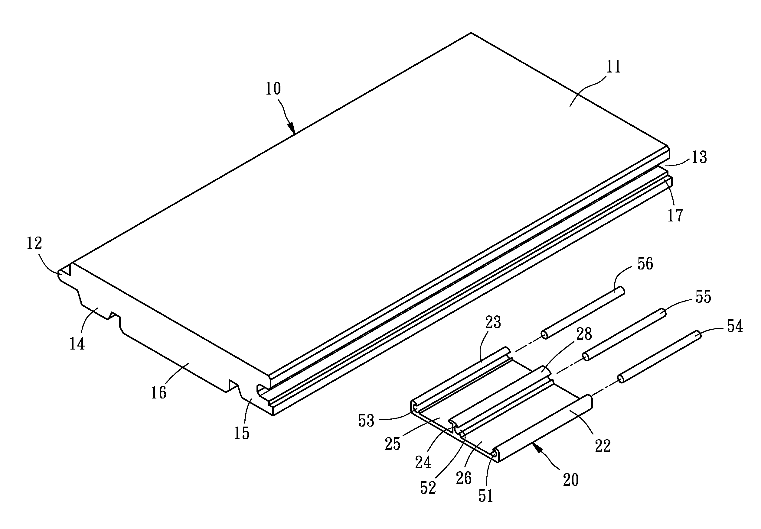
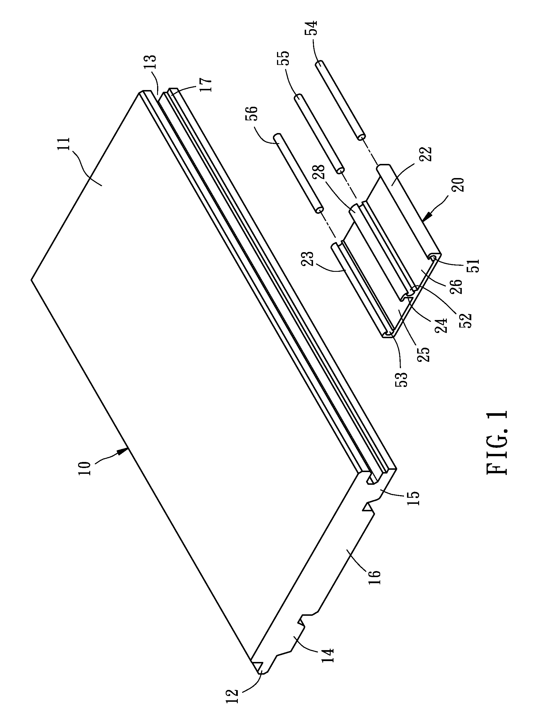
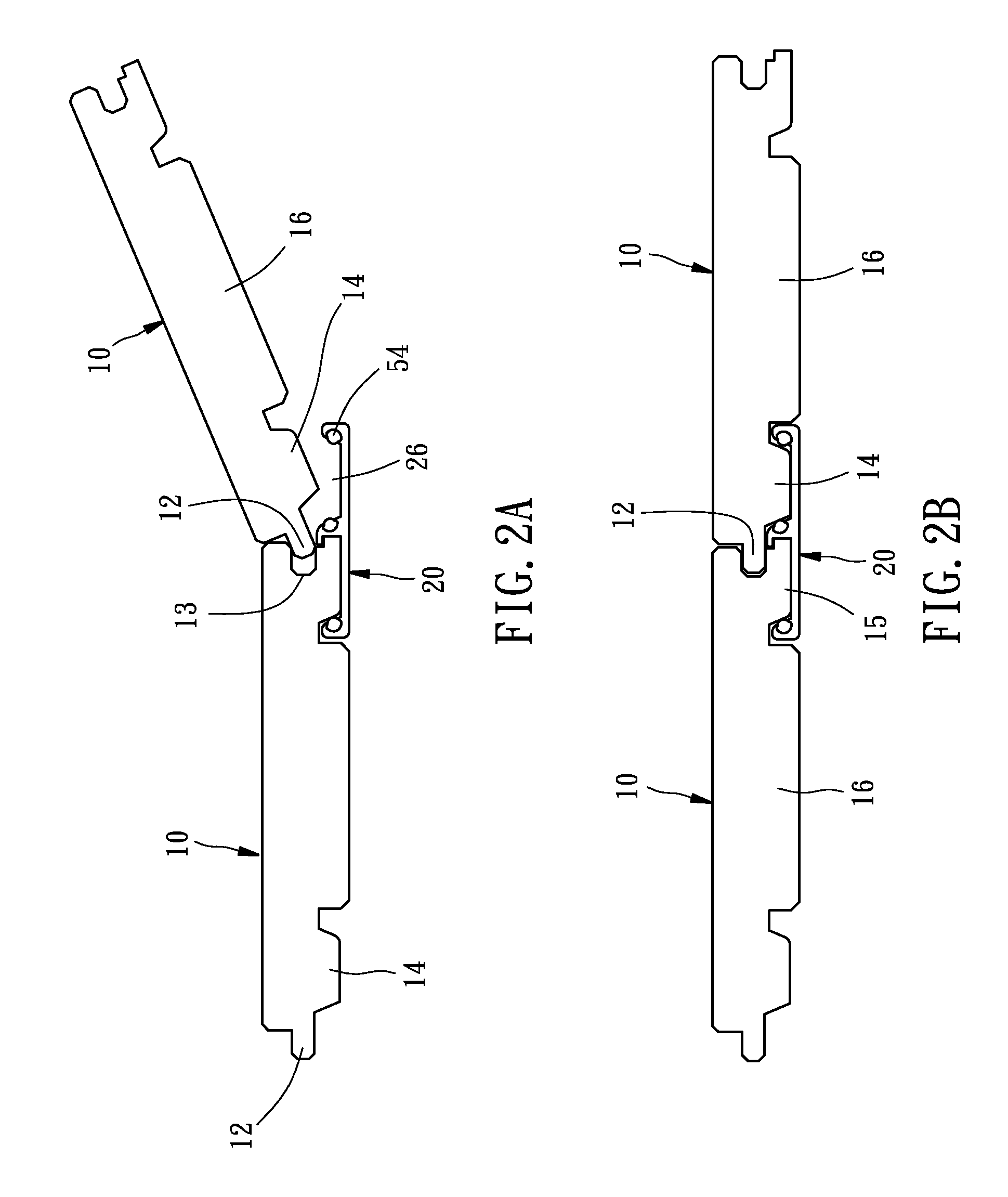
[0014]Referring to FIGS. 1-3, a modular floor 1 constructed according to a preferred embodiment of the present invention is composed of a plurality of floor panels 10 and a plurality of combination members 20.

[0015]Each of the floor panes 10 includes a rectangular main body 11, a ridge 12, an outer socket 13, a first lateral bottom portion 14, a second lateral bottom portion 15, a central bottom portion 16, and a stepped portion 17. The rectangular main body has two long sides and two short sides. The ridge 12 is formed at one of the long sides of the main body 11, extending along the long side in parallel between two distal ends of the long side. The outer socket 13 is formed at the other long side of the main body 11, extending along the long side in parallel between two distal ends of the long side. The first lateral bottom portion 14 is located below the ridge 12. The second lateral bottom portion 15 is located below the outer socket 13. The stepped portion 17 is formed at an ex...


PUM


Abstract

A modular floor is composed of a plurality of floor panels and combination members. Each of the floor panels includes a rectangular main body, a ridge formed at one side of the main body, an outer socket formed at an opposite side of the main body relative to the ridge, a first lateral bottom portion formed below the ridge, and a second lateral bottom portion formed below the outer socket. Each of the combination members includes a base, a front retainer protruding upward from one side of a top side of the base, a rear retainer protruding upward from an opposite side of the top side of the main body relative to the front retainer, and a partition protruding upward from a midsection of the top side of the base.

Description

BACKGROUND OF THE INVENTION[0001]1. Field of the Invention[0002]The present invention relates generally to building materials, and more particularly, to a modular floor.[0003]2. Description of the Related Art[0004]Most of conventional modular floors each are composed of a plurality of rectangular floor panels combined with one another. As shown in FIG. 4, a typical modular floor 70 as disclosed in Taiwan Patent No. M271046 is composed of a plurality of floor panels 71 and a plurality of combination members 72. Each of the floor panels 71 includes a first combination portion 73 and a second combination portion 74. One of the floor panels 71 is combined with the adjacent floor panel 71 by a plurality of screws 75 and some of the combination members 72, each of which has one end engaged with the second combination portion 74 and the other end thereof engaged with the first combination portion 73.[0005]However, while the modular floor 70 is installed, it may easily happen that the combi...

Claims


Application Information

Patent Timeline
Patent Type & Authority Patents(United States)
IPC IPC(8): E04B2/00
CPCE04F15/02E04F2201/0517E04F2201/0153
Inventor YANG, FENG-LING
Owner EASIKLIP FLOORS INC
Why Eureka
Try Eureka