Drop counter and flow meter for apparatus and method for determining the thermal stability of fluids

a flow meter and fluid flow technology, applied in the direction of instruments, machines/engines, material heat development, etc., can solve the problems of engine failure, reduced heat transfer efficiency, and high potential for thermally induced deposition formation, and achieve accurate measurement of the flow rate of the fuel being tested. , the effect of accurate measurement of the flow ra

Active Publication Date: 2012-10-02
PETROLEUM ANALYZER COMPANY
View PDF12 Cites 5 Cited by
  • Summary
  • Abstract
  • Description
  • Claims
  • Application Information

AI Technical Summary

Benefits of technology

[0012]It is an object of the present invention to provide an apparatus and method for testing thermal oxidation stability of fluids, particularly aviation fuels with an improved drop counter and flow meter.
[0013]It is another object of the present invention to provide an apparatus and method to measure the tendency of fuels to form deposits when in contact with heated surfaces, the apparatus including an improved drop counter and flow meter.
[0016]It is another objective of the present invention to provide an improved drop counter and flow meter to accurately measure the flow rate of the fuel being tested.
[0017]It is yet another objective of the present invention to provide a drop counter and flow meter to accurately measure the flow rate of the fuel being tested for thermal oxidation stability.

Problems solved by technology

Combined with an overall decreasing quality of feedstock material for production of fuels, the potential for thermally induced deposition formation is high.
Deposits within an aviation turbine engine can (1) reduce heat transfer efficiency, (2) block fuel filters, lines, and nozzles, or (3) result in engine failure.
However, this is difficult to perform manually due to slow rate of flow which is in drops per minute.
This can cause a problem if one or the other is misplaced or lost.
Inaccurate information and / or conclusions occur if the wrong set of data is associated with the wrong heater tube.

Method used


Image

  • Drop counter and flow meter for apparatus and method for determining the thermal stability of fluids
  • Drop counter and flow meter for apparatus and method for determining the thermal stability of fluids
  • Drop counter and flow meter for apparatus and method for determining the thermal stability of fluids

Examples


Embodiment Construction

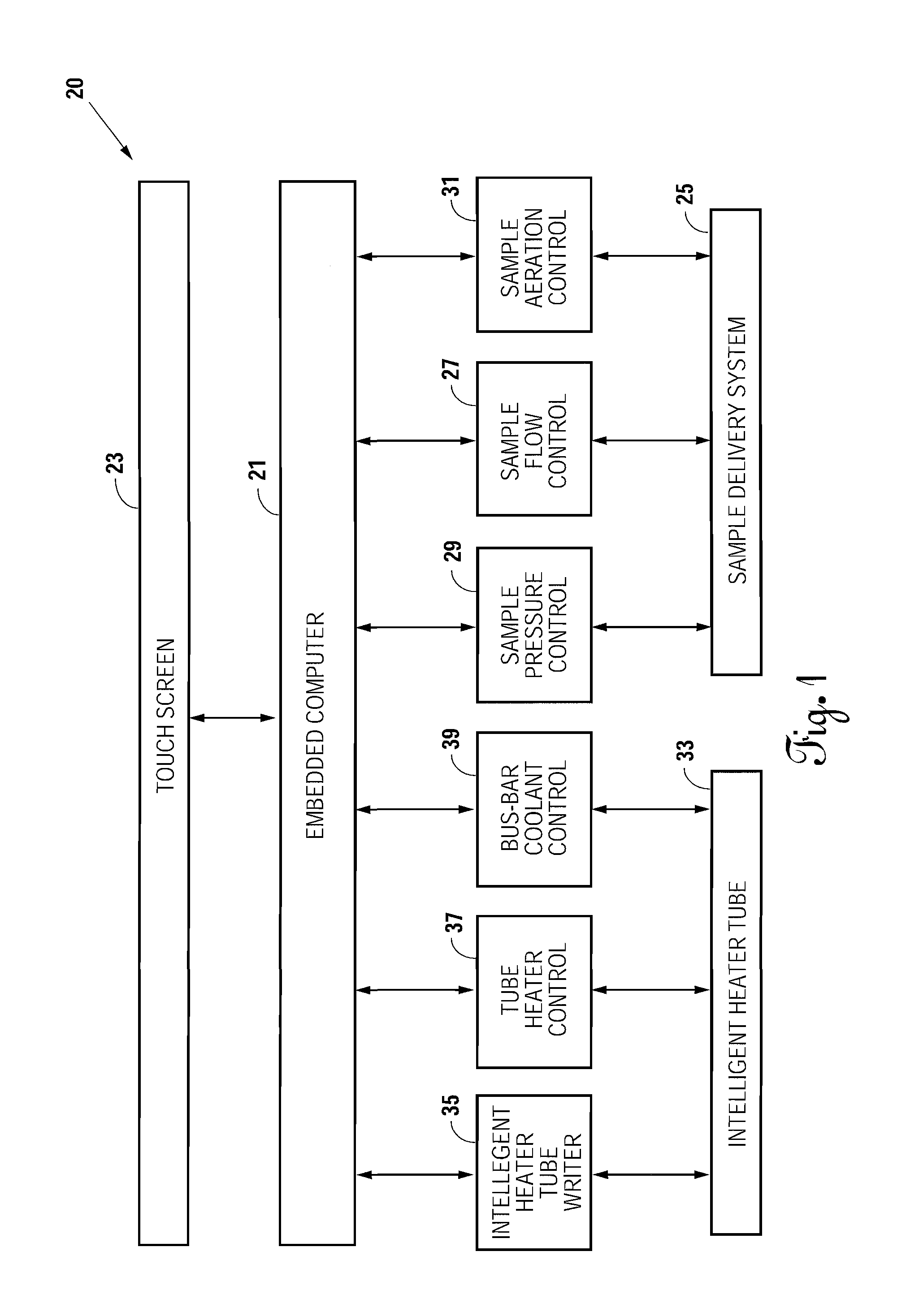
[0025]FIG. 1 is a schematic block diagram of a thermal oxidation stability tester referred to generally by the reference numeral 20. The thermal oxidation stability tester 20 has an embedded computer 21 with a touch screen 23 for user interface. While many different types of programs could be run, in the preferred embodiment, Applicant is running C++ in the embedded computer 21. The touch screen 23 displays all of the information from the thermal oxidation stability tester 20 that needs to be conveyed to the user. The user communicates back and forth with the embedded computer 21 through the touch screen 23. If a batch of fuel is to be tested, a test sample is put in the sample delivery system 25.

[0026]It is required by the test to ensure the test sample is oxygen saturated through aeration. Therefore, the embedded computer 21 operates a sample aeration control 31 for a period of time to make sure the sample is fully aerated. The aeration of the sample takes place at the beginning o...


PUM

PropertyMeasurementUnit
pressureaaaaaaaaaa
pressureaaaaaaaaaa
sizeaaaaaaaaaa

Abstract

A thermal oxidation tester is shown for determining thermal stability of a fluid, particularly hydrocarbons when subjected to elevated temperatures. The tendency of the heated fluid to oxidize and (1) form deposits on a surface of a heater tube and (2) form solids therein, are both measured at a given flow rate, temperature and time. The measured results are used to determine whether a fluid sample passes or fails the test. Sample flow rate is important in the jet fuel thermal oxidation test. Current practice requires manual drop counting or flow confirmation with the use of volumetric glassware. An apparatus is described to precisely measure the flow rate and automatically perform flow rate check using a drip rate method and / or volumetric method.

Description

CROSS REFERENCE TO RELATED APPLICATIONS[0001]This is a continuation-in-part of U.S. patent application Ser. No. 12 / 838,104, filed on Jul. 16, 2010, having at least one overlapping inventor and the same assignee, which application is incorporated herein by reference.BACKGROUND OF THE INVENTION[0002]1. Technical Field[0003]This invention relates to a drop counter and flow meter for methods and devices measuring the thermal characteristics of fluids. Specifically, this invention relates to automated flow rate check using a drop counter and / or volumetric flow meter incorporated in methods and devices measuring the thermal oxidation tendencies of fuels used in liquid hydrocarbon-burning engines.[0004]2. Background Art[0005]The development of higher performance aviation turbine engines has increased the stress placed on the fuels. In addition to being the fuel source, an aviation turbine fuels may also be used as a heat sink to cool engine components. Combined with an overall decreasing q...

Claims


Application Information

Patent Timeline
Patent Type & Authority Patents(United States)
IPC IPC(8): G01N33/22G01F23/292G01N25/00
CPCG01N33/2805
Inventor ANDERSON, DAVID G.YOUNGBLOOD, LARRY M.YANG, GUOXINGSPINO, LARRY A.BERKHOUS, SCOTT K.FANG, FANG
Owner PETROLEUM ANALYZER COMPANY
Why Eureka
Try Eureka