
Electret assembly for a microphone having a backplate with improved charge stability

a technology of electroacoustic transducers and backplates, which is applied in the field of electroacoustic transducers, can solve the problems of increasing the charge, increasing the charge, and increasing the charge, and achieves the effects of minimizing the water absorption, and minimizing the charge degradation

Inactive Publication Date: 2012-10-02
SONION NEDERLAND
View PDF37 Cites 74 Cited by
  • Summary
  • Abstract
  • Description
  • Claims
  • Application Information

AI Technical Summary

Benefits of technology

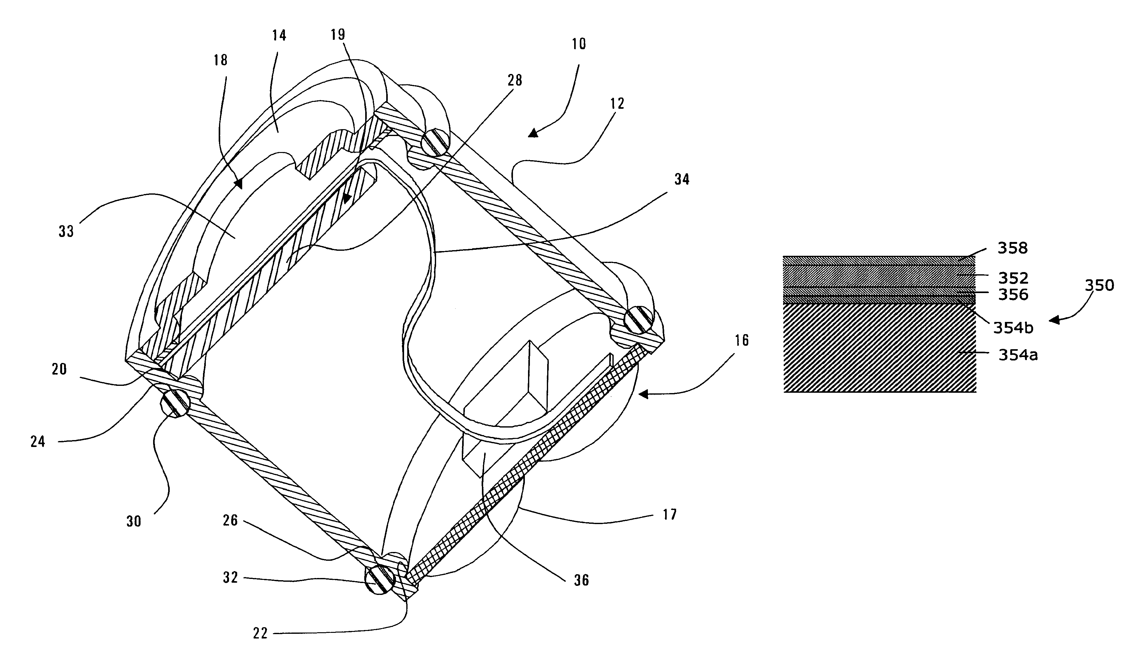
[0010]To minimize the charge degradation due to physical contact with foreign materials, the first surface of the charged layer includes a protective layer thereon to inhibit physical contact between the charged layer and foreign materials, such as moisture and dirt. The protective layer on the first surface is preferably a hydrophobic material to minimize the water absorption.
[0011]To minimize the charge degradation due to the infiltration of positive charges (i.e., holes) or negative charges (i.e., electrons) from the conductor (positive or negative depending on the polarity of the charged layer), the second surface of the charged layer includes a protective layer thereon. When the charged layer is negatively charged, the protective layer on the second surface preferably has a low “hole” conductivity to resist the movement of holes from the conductor.
[0013]Recognizing that a conductor surface that is rougher may enhance its ability to allow a charge to flow into an adjacent charged layer, the present invention also contemplates processing the conductor's surface to smooth the sharp micro-peaks that may be present on that surface. The smoother surface may be brought about by additional vacuum deposition of metal to the initial conductive layer, galvanic metal coating, and / or polishing.

Problems solved by technology

Additionally, foreign material that comes in contact with the charged layer can accelerate the charge degradation as the foreign material may have a charge that affects the charged layer.
Second, the conductive material on the conductive member that is in contact with the charged layer can release positive (i.e., holes) or negative (i.e., electrons) charges into the charged layer, causing a change in the charge.
Furthermore, extreme ambient conditions, such as temperature and humidity, and light (especially UV light) can also cause a change in the charge.

Method used


Image

  • Electret assembly for a microphone having a backplate with improved charge stability
  • Electret assembly for a microphone having a backplate with improved charge stability
  • Electret assembly for a microphone having a backplate with improved charge stability

Examples


Embodiment Construction

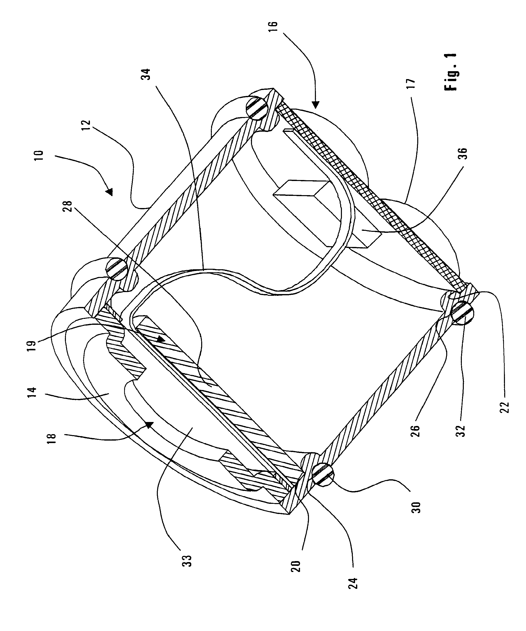
[0039]Referring to FIG. 1, a microphone 10 according to the present invention to includes a housing 12 having a cover assembly 14 at its upper end and a printed circuit board (PCB) 16 at its lower end. While the housing 12 has a cylindrical shape, it can also be a polygonal shape, such as one that approximates a cylinder. In one preferred embodiment, the axial length of the microphone 10 is about 2.5 mm, although the length may vary depending on the output response required from the microphone 10.

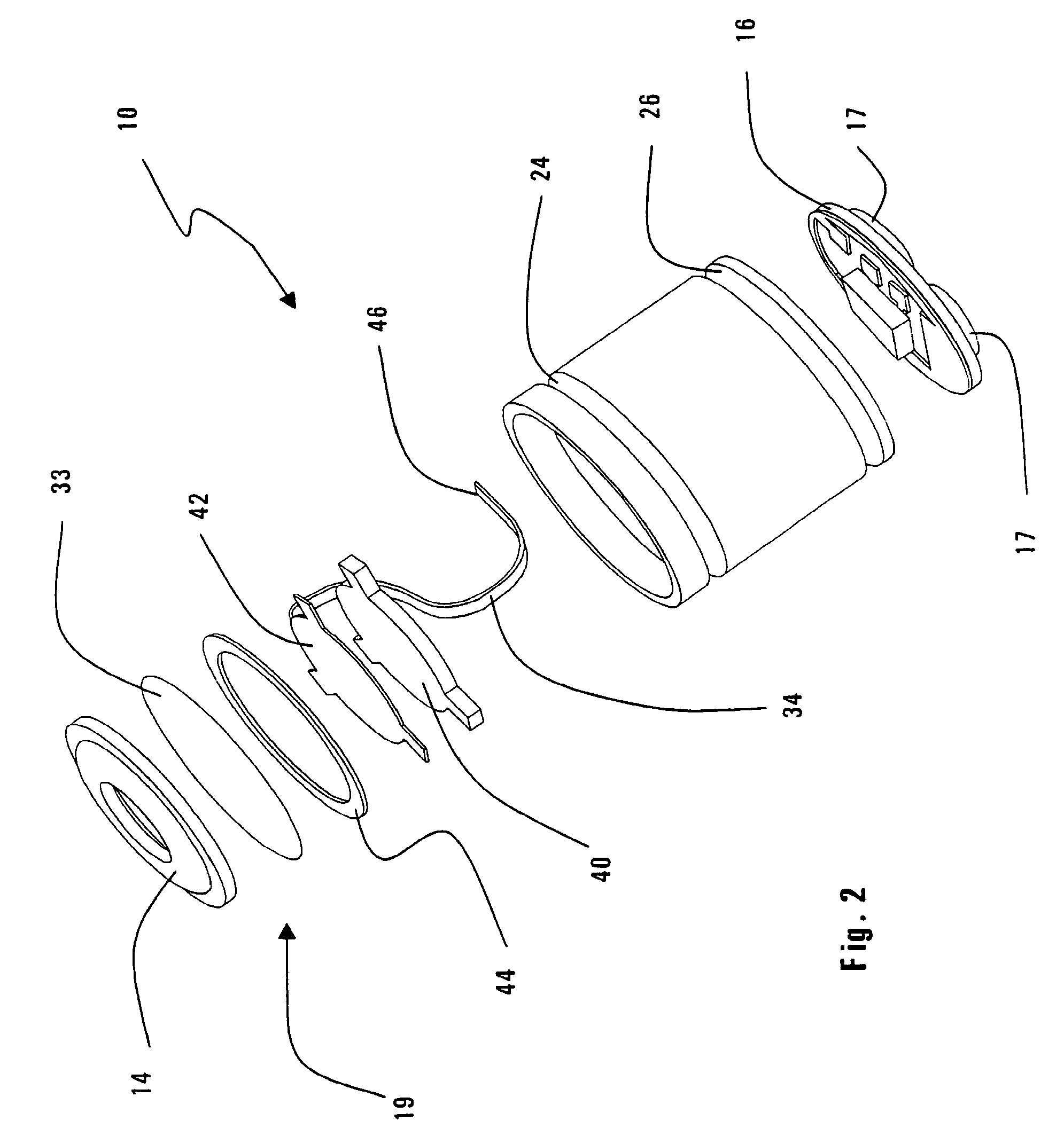
[0040]The PCB 16 includes three terminals 17 (see FIG. 2) that provide a ground, an input power supply, and an output for the processed electrical signal corresponding to a sound that is transduced by the microphone 10. The sound enters the sound port 18 of the cover assembly 14 and encounters an electret assembly 19 located a short distance below the sound port 18. It is the electret assembly 19 that transduces the sound into the electrical signal.

[0041]The microphone 10 includes an upper ...


PUM

PropertyMeasurementUnit
lengthaaaaaaaaaa
radial lengthaaaaaaaaaa
heightaaaaaaaaaa

Abstract

The present invention relates to a microphone that includes a housing and a diaphragm and backplate located with the housing. The housing has a sound port for receiving the sound. The diaphragm undergoes movement relative to the backplate, which it opposes, in response to the incoming sound. The backplate has a charged layer with a first surface that is exposed to the diaphragm and a second surface opposite the first surface. The backplate further includes a conductor for transmitting a signal from the backplate to electronics in the housing. The conductor faces the second surface of the charged layer. To minimize the charge degradation created by contact with or infiltration of foreign materials, the first surface, the second surface, or both surfaces of the charged layer includes a protective layer thereon.

Description

RELATED APPLICATIONS[0001]This application is a continuation-in-part of U.S. patent application Ser. No. 10 / 210,571, filed Aug. 1, 2002; which is a continuation-in-part of U.S. patent application Ser. No. 10 / 124,683, filed Apr. 17, 2002; which claims the benefit of priority of U.S. Provisional Patent Application Nos. 60 / 301,736, filed Jun. 28, 2001, and 60 / 284,741, filed Apr. 18, 2001. These four applications are incorporated herein by to reference in their entireties.RELATED APPLICATIONS[0002]This application is a divisional of U.S. patent application Ser. No. 11 / 544,418, filed Oct. 6, 2006, now allowed, which is a divisional of U.S. patent application Ser. No. 10 / 266,799, filed Oct. 8, 2002, now issued as U.S. Pat. No. 7,136,496 on Nov. 14, 2006, which is a continuation-in-part of U.S. patent application Ser. No. 10 / 210,571, filed Aug. 1, 2002, now issued as U.S. Pat. No. 6,937,735 on Aug. 30, 2005, which is a continuation-in-part of U.S. patent application Ser. No. 10 / 124,683, fi...

Claims


Application Information

Patent Timeline
Patent Type & Authority Patents(United States)
IPC IPC(8): H04R25/00H04R1/04H04R19/01
CPCH04R1/04H04R19/016H04R19/04Y10T29/49002H04R25/00
Inventor VAN HALTEREN, AART Z.MARISSEN, ROELOF A.BOSMAN, MICHELDE ROO, DION I.MOGELIN, RAYMONDDE NOOIJ, MICHEL
Owner SONION NEDERLAND
Learn More