
System and method for tuning FM synthesizer

a synthesizer and tuning system technology, applied in pulse generators, pulse manipulation, pulse techniques, etc., can solve problems such as difficult implementation and significant challenges, and achieve the effect of reducing the required capacitance change and reducing the required range of output frequencies

Active Publication Date: 2012-10-02
TEXAS INSTR INC
View PDF9 Cites 0 Cited by
  • Summary
  • Abstract
  • Description
  • Claims
  • Application Information

AI Technical Summary

Benefits of technology

The present invention aims to reduce the tuning range of a DCO (Digital-to-analog converter) by increasing the capability of a frequency divider. This helps to minimize the required change in capacitance when adjusting the DCO. Additionally, the invention provides a device and method for dividing a clock signal by both even and odd integers. This is achieved by a divider, a delay portion, and a duty cycle corrector. The invention offers improved accuracy and efficiency in clock signal division.

Problems solved by technology

As the required frequency range of DCO 212 increases, the corresponding range of the capacitors must increase, which can lead to significant challenges due to parasitic capacitance.
This is very difficult to implement because of parasitic capacitance in DCO 212.

Method used


Image

  • System and method for tuning FM synthesizer
  • System and method for tuning FM synthesizer
  • System and method for tuning FM synthesizer

Examples


Embodiment Construction

[0048]In accordance with an aspect of the present invention, an output processor addresses the challenges associated with generating the necessary synthesizer output clock signals. This is accomplished by utilizing both even and odd divisors, expanding the output range of the output divider 214, while minimizing the tuning range needed for DCO 212.

[0049]Aspects in accordance to the present invention will now be described below with reference to FIG. 5 through FIG. 7.

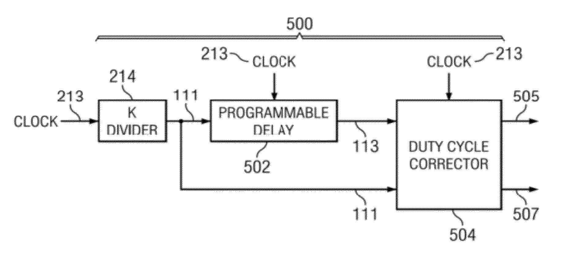
[0050]FIG. 5 illustrates an output processor 500, in accordance with an aspect of the present invention.

[0051]Output processor 500 includes output divider 214, a programmable delay 502 and a duty cycle corrector 504.

[0052]Output divider 214 is arranged to receive output clock signal 213 and to output I-signal 111. Programmable delay 502 is arranged to receive output clock signal 213 and I-signal 111 and to output a delayed Q-signal 113. Duty cycle corrector 504 is arranged to receive I-signal 111 and Q-signal 113 and to ...


PUM


Abstract

A device is provided for dividing a clock signal by even and odd integers. The device includes a divider, a delay portion and a duty cycle corrector. The divider is arranged to receive the clock signal and can divide the clock signal and output a divided clock signal. The delay portion can output a delayed signal based on the divided clock signal. The duty cycle corrector can output a first signal based on the delayed signal and the divided clock signal.

Description

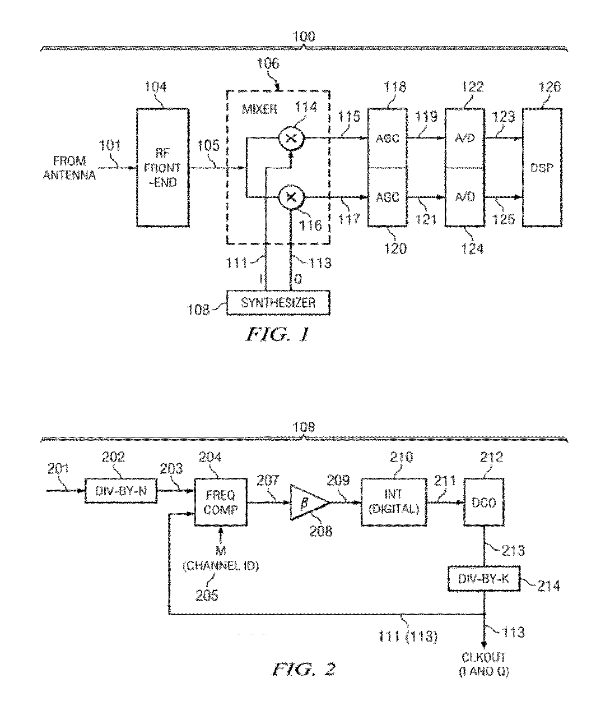
[0001]The present application claims priority from U.S. Provisional Application No. 61 / 113,648 filed Nov. 12, 2008, the entire disclosure of which is incorporated herein by reference.BACKGROUND[0002]A conventional receiver receives radio frequency signals and attenuates noise from the received radio frequency signals so that a desired signal can be converted for the use of video, voice, or data. Conventional receivers are used in military, wireless, satellite communications, microwave and other technologies. From an antenna, a conventional receiver is tuned to extract the desired radio signal. The transmitted signal will have been modulated in one of several ways, for instance, amplitude modulation (AM) or frequency modulation (FM). A conventional FM receiver will now be described below with reference to FIG. 1.[0003]FIG. 1 illustrates a conventional FM receiver 100. Receiver 100 includes an RF front end 104, a mixer 106, an FM synthesizer 108, an automatic gain controller (AGC) 118...

Claims


Application Information

Patent Timeline
Patent Type & Authority Patents(United States)
IPC IPC(8): H04B1/06
CPCH03K5/1565H03L7/18
Inventor NAGARAJ, KRISHNASAWAMYNAYAK, NEERAJ
Owner TEXAS INSTR INC
Learn More