
Power assist device and its control method

a technology of assist device and power supply, which is applied in the direction of manipulators, program control, instruments, etc., can solve the problems of robot vibration, oscillation phenomenon, oscillation phenomenon, etc., and achieve the effects of suppressing oscillation phenomenon, preventing oscillation phenomenon, and maintaining stable connection sta

Active Publication Date: 2012-10-02
TOYOTA JIDOSHA KK +1
View PDF12 Cites 9 Cited by
  • Summary
  • Abstract
  • Description
  • Claims
  • Application Information

AI Technical Summary

Benefits of technology

[0018]According to the power assist device of the present invention, when the power assist device is brought into contact with the environment, the oscillation phenomenon is prevented and the stable connection state is maintained.
[0019]According to the power assist device of the present invention, instead of correcting the operation force, the external force is corrected to be limited so as to suppress the oscillation phenomenon on the power assist device without spoiling the operability.
[0020]According to the power assist device of the present invention, the oscillation phenomenon on the power assist device is suppressed more certainly without spoiling the operability.
[0021]According to the control method of the power assist device of the present invention, when the power assist device is brought into contact with the environment, the oscillation phenomenon is prevented and the stable connection state is maintained.
[0022]According to the control method of the power assist device of the present invention, instead of correcting the operation force, the external force is corrected to be limited so as to suppress the oscillation phenomenon on the power assist device without spoiling the operability.
[0023]According to the control method of the power assist device of the present invention, the oscillation phenomenon on the power assist device is suppressed more certainly without spoiling the operability.

Problems solved by technology

However, in this control method, there is known that, when an operator brings the robot into contact with the environment and then presses the robot to the environment further, the robot vibrates along the pressing direction and the anti-pressing direction (so-called oscillation phenomenon occurs).
However, even slight difference between the two causes the oscillation phenomenon.
The oscillation phenomenon becomes a problem in the case that the connection of the robot with the environment is premised such as pressing work with a power assist device.
However, in this case, another problem occurs that the operation force required for the operation of the power assist device is increased so as to worsen the operability, whereby it is undesirable in practical use.
Namely, with regard to the conventional art, there is no method effective to suppress the oscillation phenomenon caused in the pressing work with the power assist device.

Method used


Image

  • Power assist device and its control method
  • Power assist device and its control method
  • Power assist device and its control method

Examples


Embodiment Construction

[0029]Explanation will be given on the mode for carrying out the invention referring appended drawings.

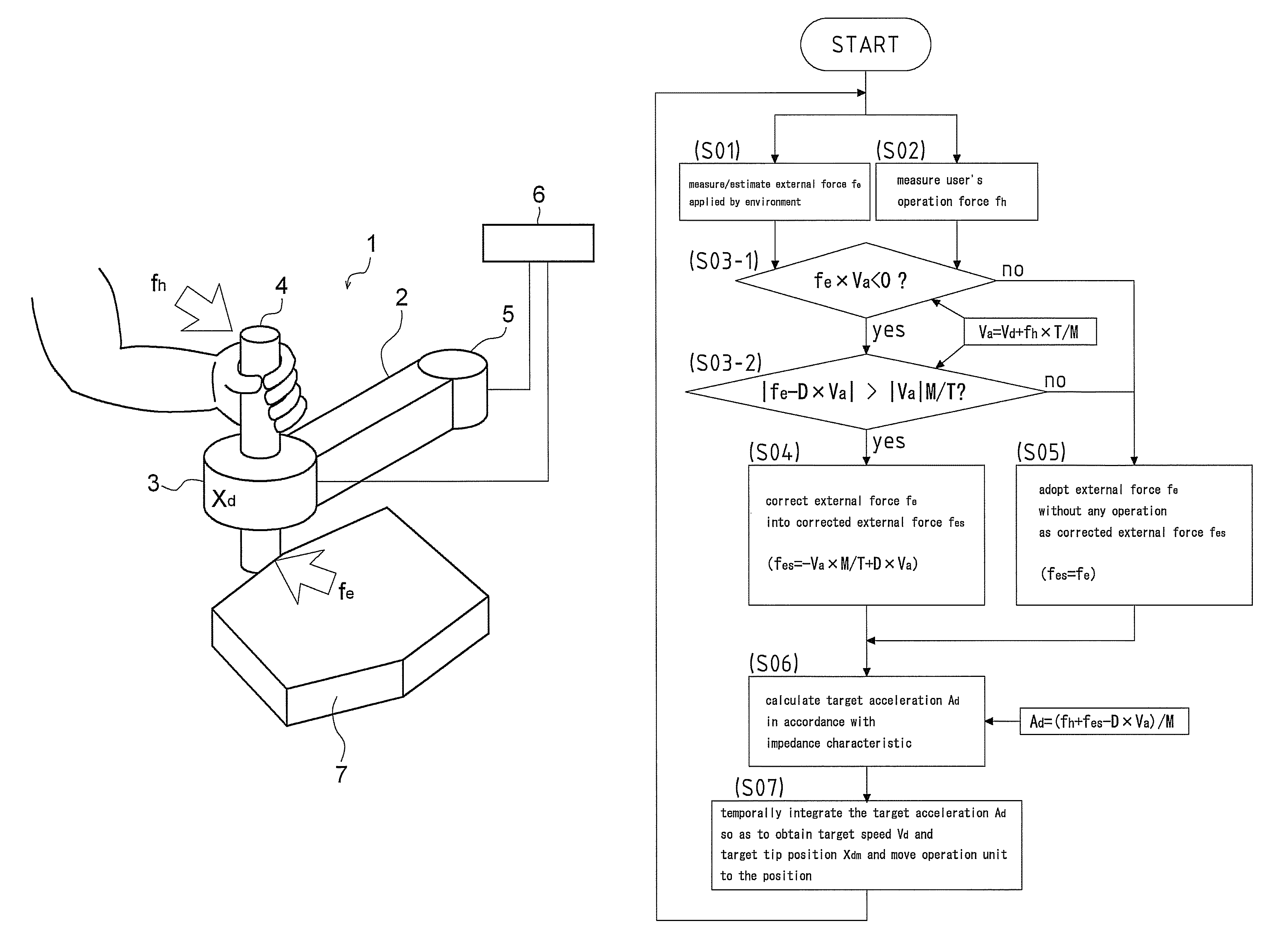
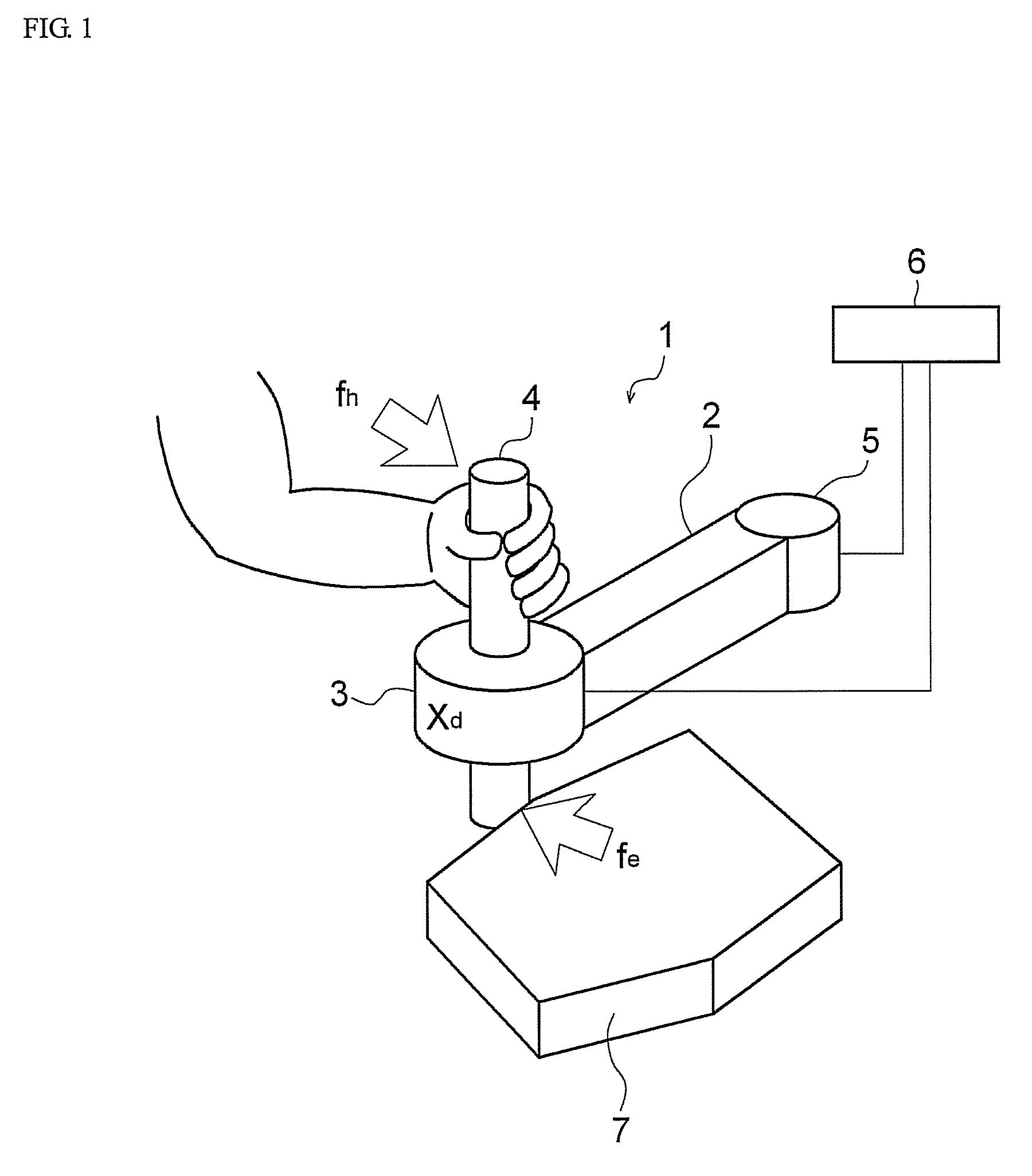
[0030]Firstly, explanation will be given on a power assist device 1 and control method thereof according to an embodiment of the present invention referring work shown in FIG. 1 as an example.

[0031]As shown in FIG. 1, the power assist device 1 includes a robot arm 2, an inner force sensor 3, an operation handle 4, an actuator 5, a control device 6 and the like.

[0032]The robot arm 2 is supported by the actuator 5 which is a drive means, and the robot device can assume various postures by the actuation of the actuator 5 following commands from the control device 6.

[0033]The operation handle 4 which is an operation part is disposed at the tip of the robot arm 2 through the inner force sensor 3 which is an operation force detection means, and an operator can moves the robot arm 2 to a desired position by holding the operation handle 4. The operation force applied on the operation handl...


PUM


Abstract

It is possible to provide a power assist device which can maintain a stable contact state without causing an oscillation phenomenon even if a robot is brought into contact with an environment. A method for controlling the power assist device is also provided. The power assist device includes: an inner force sensor which detects an operation force applied by an operator; an operation handle having the inner force sensor; a robot arm which supports the operation handle; an actuator which drives the robot arm; the actuator and a control device which measure or estimate a force applied when the robot arm is brought into contact with an environment; and the actuator and the control device which detect or estimate a motion speed of the operation handle. The control device acquires a corrected external force according to the operation force detected by the inner force sensor and an external force detected by the actuator and the control device as external force derivation means and controls the actuator so that the corrected external force acts on the operation handle.

Description

[0001]This is a 371 national phase application of PCT / JP2008 / 066212 filed 9 Sep. 2008, which claims priority to Japanese Patent Application No. 2007-237034 filed 12 Sep. 2007, the contents of which are incorporated herein by reference.FIELD OF THE INVENTION[0002]The present invention relates to a power assist device and its control method.BACKGROUND OF THE INVENTION[0003]Conventionally, at the scene of manufacture, a robot referred to as a power assist device is used so as to reduce labor and improve workability. As a control method of the power assist device, mechanical impedance control based on a position control (called an admittance control) is widely adopted.[0004]In the admittance control, normally, position control with a high gain is performed and its target position is determined based on a force sensor. Then, force applied on the power assist device not through the force sensor is not considered at the control action, and a manipulator is hardly actuated. Namely, when the...

Claims


Application Information

Patent Timeline
Patent Type & Authority Patents(United States)
IPC IPC(8): B25J13/08
CPCB25J13/02G05B19/423G05B2219/39339G05B2219/36429B25J13/025
Inventor TAKESUE, NAOYUKIFUJIMOTO, HIDEO
Owner TOYOTA JIDOSHA KK
Learn More