Supercharge Your Innovation With Domain-Expert AI Agents!

Accelerator operating device

a technology of operating device and accelerator, which is applied in the direction of mechanical control device, cycle equipment, instruments, etc., can solve the problems of difficult control of hysteresis, and risk that the throttle grip will not return to the rest position, etc., and achieves simple configuration, large hysteresis characteristics, and control of hysteresis.

Active Publication Date: 2012-10-09
MIKUNI CORP
View PDF28 Cites 1 Cited by
  • Summary
  • Abstract
  • Description
  • Claims
  • Application Information

AI Technical Summary

Benefits of technology

[0010]In view of the above circumstances of the conventional device described above, an aspect of the present invention is to provide an accelerator operating device by which, while making the assembly and maintenance tasks easier by simplifying the structure, miniaturizing, and reducing the number of parts, unpleasant feeling can be resolved by exerting a desirable load on the rotational operating force; hysteresis characteristics can be provided to the rotational operating force corresponding to the opening rotation and closing rotation; and failsafe functions can be further guaranteed.

Problems solved by technology

Nonetheless, the above accelerator operating device requires a plurality of coil springs to apply pressure on the friction plate as the load generation mechanism that generates load on the rotational operating force, and therefore, the structure is complicated, and tasks such as assembly and maintenance are laborious.
Moreover, if sticking or the like occurs between the friction plate and the drive gear, there is the risk that the throttle grip will not return to the rest position (throttle closed angle position).
Further, regarding rotational operating force of the throttle grip, even if a constant frictional force (load) can be generated in addition to the counterforce of the return spring, the hysteresis characteristics of the rotational operating force cannot be changed by increasing or decreasing the frictional force (load) corresponding to the increase of the opening angle of the throttle grip.

Method used


Image

  • Accelerator operating device
  • Accelerator operating device
  • Accelerator operating device

Examples


Embodiment Construction

[0041]Reference will now be made in detail to the embodiments, examples of which are illustrated in the accompanying drawings, wherein like reference numerals refer to the like elements throughout. The embodiments are described below to explain the present invention by referring to the figures.

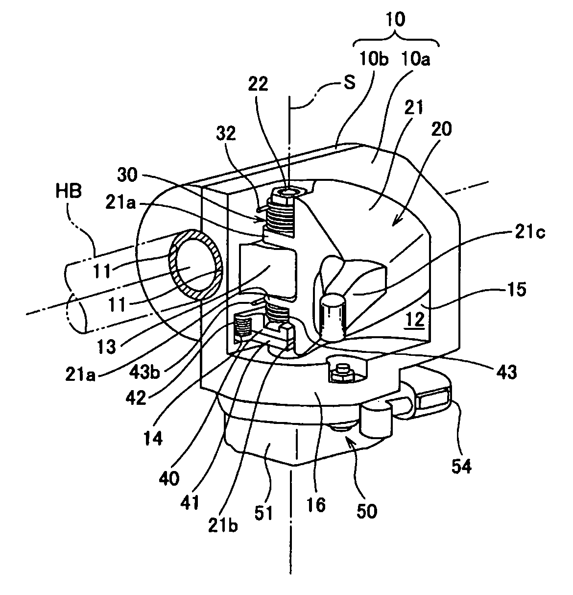
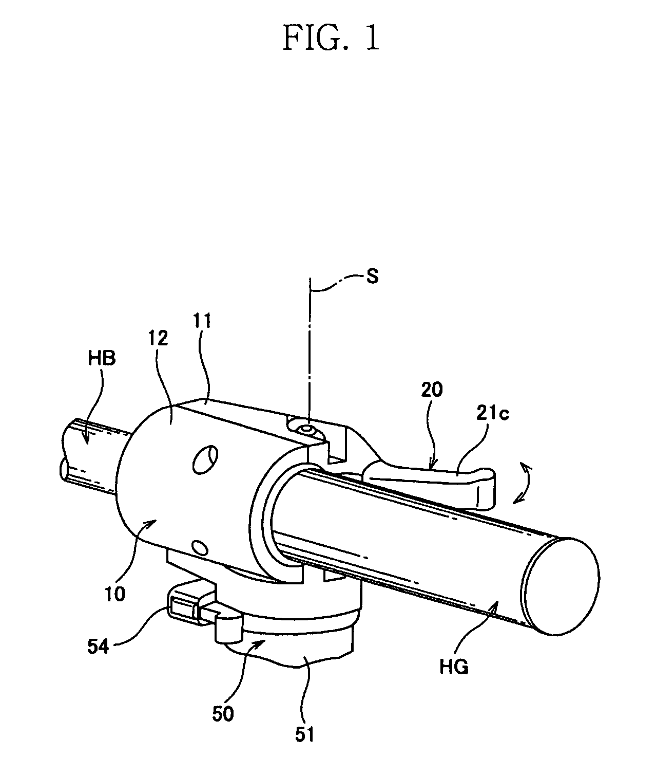
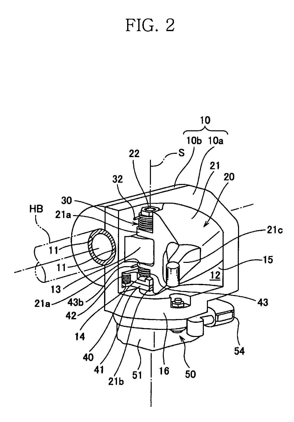
[0042]FIG. 1 to FIG. 6 indicate one embodiment of an accelerator operating device. FIG. 1 is perspective view indicating the accelerator operating device mounted on a two-wheeled vehicle; FIG. 2 is a perspective view of the accelerator operating device; FIG. 3 is cross-sectional perspective view indicating the interior of the accelerator operating device; FIG. 4 is a longitudinal cross-section indicating the interior of the accelerator operating device; FIG. 5 is a schematic diagram indicating the load generating mechanism included in the accelerator operating device; and FIG. 6 is a characteristics diagram indicating the characteristics of the rotational operating force of the accelerator lev...


PUM


Abstract

An accelerator operating device including a body fixed to a handlebar; an accelerator lever supported on the body so as to rotate freely around a predetermined axial line and that rotates between a close position and a maximum open position; a first return spring that returns the accelerator lever to the close position; and a load generation mechanism that generates a load on a rotational operating force of the accelerator lever by frictional resistance. The load generating mechanism includes a rotational slider arranged to freely rotate around the axial line that can be pressed and rotated by opening rotation of the accelerator lever; a slide receiving part formed in the body that allows the rotational slider to slide; a biasing spring that biases the rotational slider toward the slide receiving part; and a second return spring that returns the rotational slider to a rest position.

Description

CROSS-REFERENCE TO RELATED APPLICATIONS[0001]This application is based upon and claims the priority benefit of Japanese Application No. 2008-284969, filed Nov. 6, 2008, in the Japanese Intellectual Property Office, the disclosure of which is incorporated herein by reference.BACKGROUND[0002]1. Field[0003]The present invention relates to an accelerator operating device provided on the handle of a two-wheeled vehicle and the like, and more particularly relates to an accelerator operating device employing a drive-by-wire system.[0004]2. Description of the Related Art[0005]A well-known conventional accelerator operating device includes: a dual partitioned case installed on the handlebar; a throttle grip installed to rotate freely on the end of the handlebar; a gear mechanism containing a drive gear and a detection gear that are included in the case and rotate around the handlebar; a tube guide that is arranged to freely rotate around the handlebar and transmits the rotation of the thrott...

Claims


Application Information

Patent Timeline
Patent Type & Authority Patents(United States)
IPC IPC(8): B62M25/04
CPCB62K23/06Y10T74/20396Y10T74/20287
Inventor OGURA, TAKAHIRO
Owner MIKUNI CORP
Features
  • R&D
  • Intellectual Property
  • Life Sciences
  • Materials
  • Tech Scout
  • Unparalleled Data Quality
  • Higher Quality Content
  • 60% Fewer Hallucinations
Learn More