Run flat tire

a technology of running flat tire and tire, which is applied in the direction of wheels, vehicle components, transportation and packaging, etc., can solve the problems of tire slipping on icy road surfaces, tire deterioration, tire wear and tear, etc., and achieves the effect of increasing the compression stiffness, increasing the out-of-plane stiffness, and driving stability in running

Inactive Publication Date: 2012-10-09
THE YOKOHAMA RUBBER CO LTD
View PDF46 Cites 1 Cited by
  • Summary
  • Abstract
  • Description
  • Claims
  • Application Information

AI Technical Summary

Benefits of technology

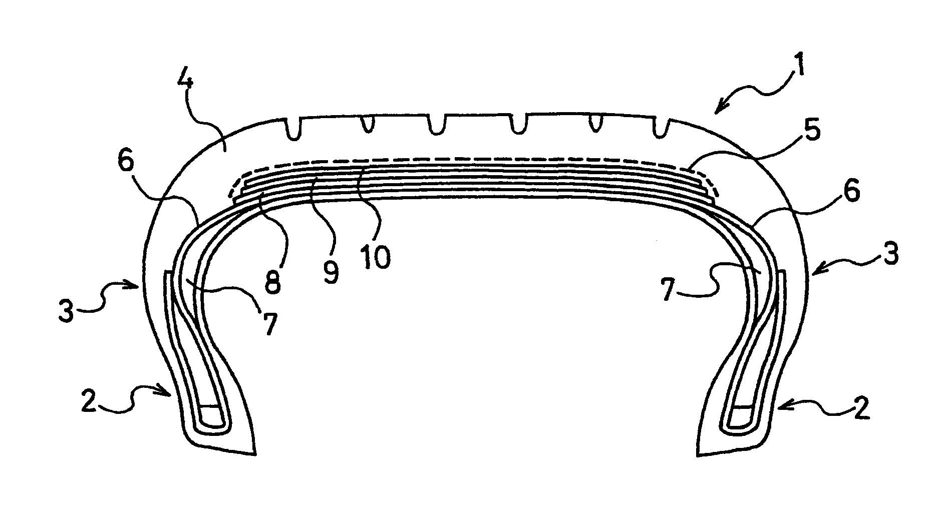
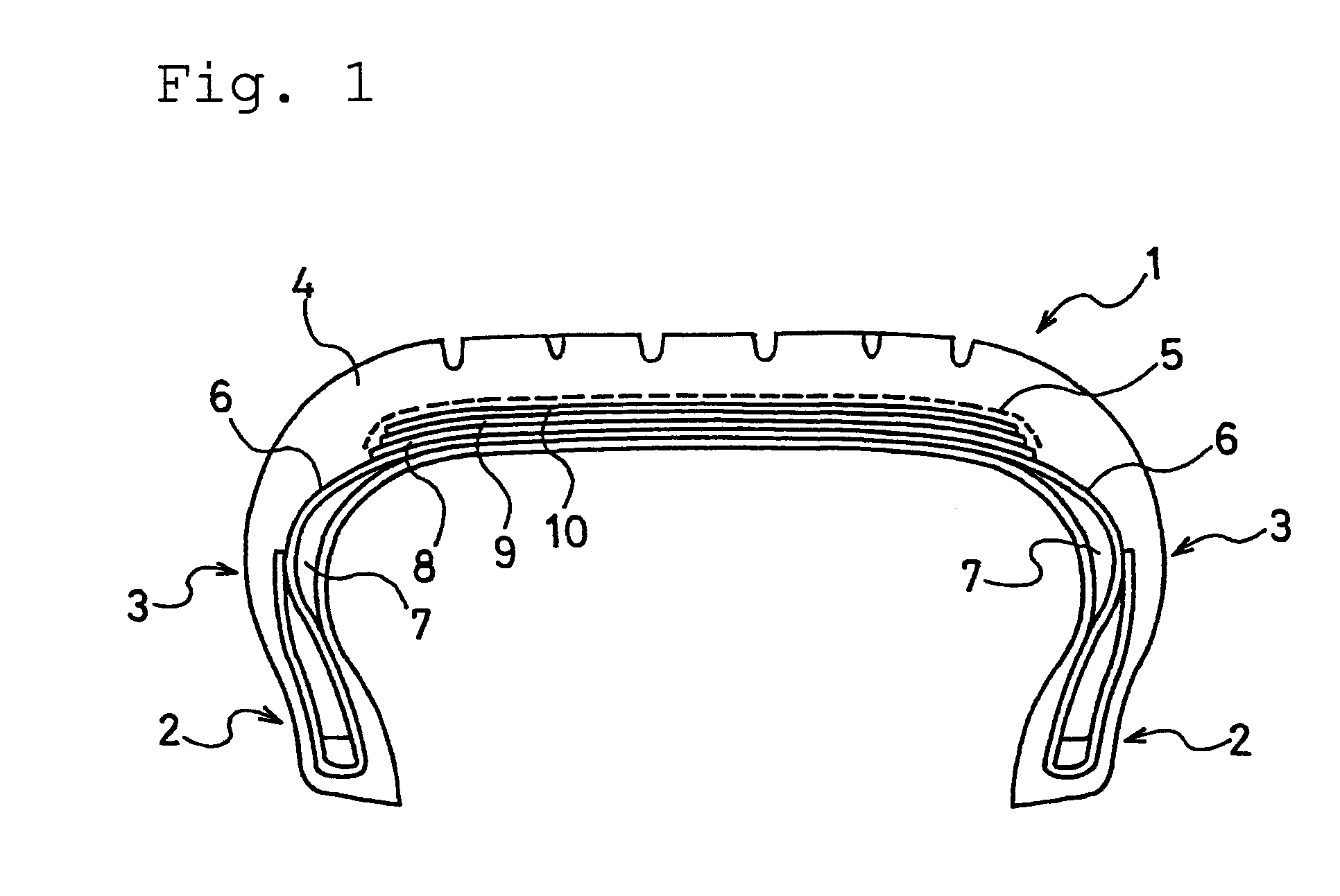
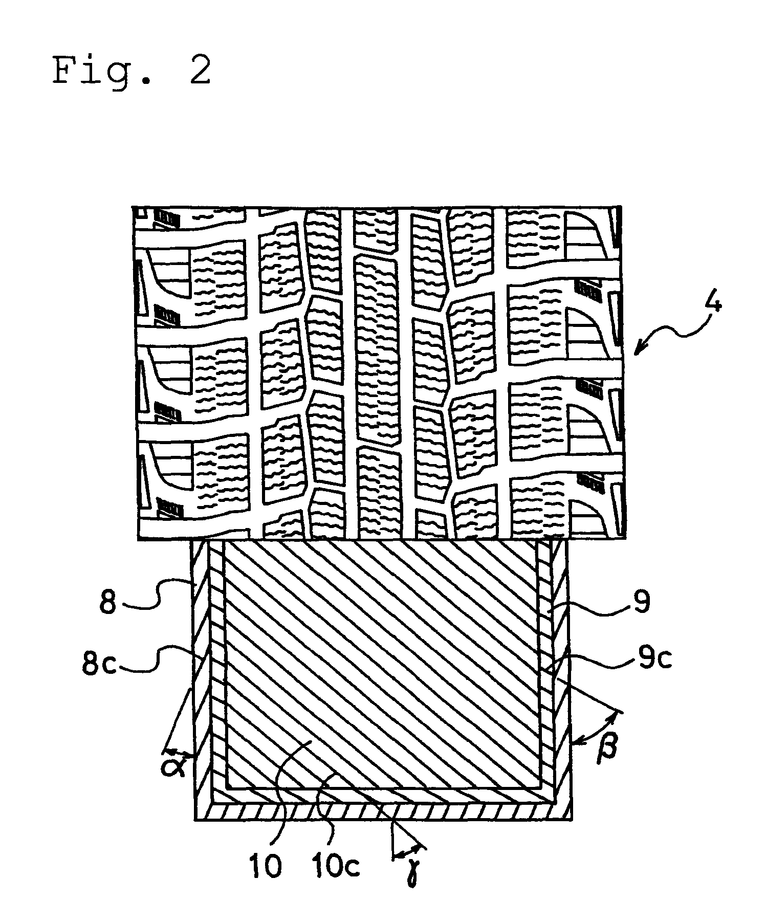
[0018]According to the first one of the present invention, the cord angle of each of the three belt layers, disposed in the tread portion, with respect to the circumferential direction of the tire is set as follows. Specifically, the cord angle α of the innermost belt layer is set at 15° to 30°, the cord angle β of the intermediate belt layer is set at not less than 40°, and the cord angle γ of the outermost belt layer is set at 35° to 70°. This configuration increases the compression stiffness, in the width direction, of the tread portion while suppressing an increase in out-of-plane stiffness in the circumferential direction as the entire belt layers. For this reason, while the ride comfort in running on general road surfaces and the driving stability in running on snowy road surfaces at the time when the tire is not punctured are enhanced, the buckling phenomenon in run-flat running where the tire is punctured is suppressed. Accordingly, because the area of the contact patch of the tire is secured, the maneuverability (particularly, the starting performance) on icy road surfaces can be enhanced.
[0019]According to the second one of the present invention, the cord angle of each of the three belt layers, disposed in the tread portion, with respect to the circumferential direction of the tire is set as follows. Specifically, each of the cord angle α of the innermost belt layer and the cord angle γ of the outermost belt layer is set to be a high angle of 40° to 75°, and the cord angle β of the intermediate belt layer is set to be a low angle of 0° to 35°. Moreover, the cord directions of the innermost belt layer and the intermediate belt layer are arranged to intersect each other with respect to an equatorial plane of the tire. This configuration makes it possible to secure, in a balanced manner, the out-of-plane stiffness in the width direction while suppressing an increase in out-of-plane stiffness in the circumferential direction as the entire belt layers. The compression stiffness, in the width direction, of the tread portion thus can be increased. For this reason, while the ride comfort in running on general road surfaces and the driving stability in running on snowy road surfaces at the time when the tire is not punctured are enhanced, the buckling phenomenon in run-flat running where the tire is punctured is suppressed. Accordingly, the maneuverability on icy road surfaces can be enhanced.

Problems solved by technology

However, the run flat tire of this type has the following problem because the load of the vehicle is supported by the hard rubbers on both of the left and right sides as described above.
Accordingly, the maneuverability in running on a low friction road surface is deteriorated.
In particular, in the case of a tire, such as a studless tire, that is designed to have a tread with low stiffness, this tendency of the deterioration is significant, so that the tire is eventually slipped on icy road surfaces.
However, this approach causes a significantly excessive increase in stiffness of the tread because three belt layers are formed in total.
As a result, this approach brings about a problem that the ride comfort in running on general road surfaces and the driving stability on snowy road surfaces at the time when the tire is not punctured are deteriorated.

Method used


Image

  • Run flat tire
  • Run flat tire
  • Run flat tire

Examples


examples 8 and 9

[0062]Examples 8 and 9 were prepared by varying, as shown in Table 2, the total cross-sectional area of the cords included in one of the outermost belt layer and the intermediate belt layer of the tire of Example 1. It should be noted that the total cross-sectional areas of the cords per unit width are shown by indices where the total cross-sectional area of the cords per unit area in the above-described conventional tire (Conventional Example) is taken as 100.

[0063]These two types of tires were evaluated, by the same testing methods as described above, in terms of the ride comfort in running on general road surfaces and the driving stability in running on snowy road surfaces at the time when the tire is not punctured, as well as the starting performance on icy road surfaces in run-flat running. The results of the evaluation are shown in Table 2, along with the result of the conventional tire (Conventional Example) shown in Table 1.

[0064]

TABLE 2ConventionalExampleExampleExample89Inn...


PUM


Abstract

Provided is a run flat tire having an enhanced ride comfort in running on general road surfaces and an enhanced driving stability on snowy road surfaces at the time when the tire is not punctured, as well as an enhanced maneuverability, particularly starting ability, on icy road surfaces in run-flat running where the tire is punctured. Three belt layers (8, 9, 10) are disposed on an outer circumferential side of a carcass layer (6) in a tread portion (4). In addition, as to the three belt layers, the cord angle α of the innermost belt layer (8) with respect to a circumferential direction of the tire is set at 15° to 30°, the cord angle β of the intermediate belt layer (9) with respect to the circumferential direction of the tire is set at not less than 40°, and the cord angle γ of the outermost belt layer (10) with respect to the circumferential direction of the tire is set at 35° to 70°.

Description

[0001]This application is a U.S. National Phase of International Application No. PCT / JP2007 / 051100 filed Jan. 24, 2007.TECHNICAL FIELD[0002]The present invention relates to a run flat tire. More specifically, the present invention relates to a run flat tire having an enhanced maneuverability, particularly starting ability, on icy road surfaces in run-flat running where the tire is punctured, while having an enhanced ride comfort in running on general road surfaces as well as an enhanced driving stability on snowy road surfaces at the time when the tire is not punctured.BACKGROUND ART[0003]Heretofore, the following run flat tire has been widely known that enables a safety driving for a certain distance even when the tire is punctured. In this run flat tire, hard rubber layers each having a crescent shape in the lateral cross section are disposed respectively in sidewall portions of the tire (for example, see Patent Documents 1 and 2). When punctured to have a pressure of zero, the ru...

Claims


Application Information

Patent Timeline
Patent Type & Authority Patents(United States)
IPC IPC(8): B60C9/18B60C9/20B60C17/00
CPCB60C9/2009B60C9/22B60C17/0009Y10T152/10792Y10T152/10801Y10T152/10765B60C2017/0081
Inventor SUGITANI, KENICHIROHASHIMOTO, YOSHIMASA
Owner THE YOKOHAMA RUBBER CO LTD
Why Eureka
Try Eureka