Cutting valve and method for making portions

a cutting valve and portion technology, applied in the field of cutting valves, can solve the problems of product parts getting damaged, limiting the maximum portion size, and not optimum cutting function, and achieve the effect of free drawing cu

Active Publication Date: 2012-10-09
ALBERT HANDTMANN MASCHFABRICK
View PDF19 Cites 6 Cited by
  • Summary
  • Abstract
  • Description
  • Claims
  • Application Information

AI Technical Summary

Benefits of technology

[0008]Since the partitioning piston is drivable during partitioning to carry out a helical movement with simultaneous translatory and rotatory movement components, a draw cut is carried out by the cutting edge in the mass strand, the draw cut treating fibrous or lumpy product constituents in an optimal gentle way and neatly cutting off the same. The helical movement can advantageously be performed with a single drive e.g. for the partitioning piston, resulting in a simple and compact structure of the cutting valve. Furthermore, the clean cutting conditions and the gentle treatment of the mass yield portion weights that are exactly observed.
[0020]In a constructionally simple embodiment the partitioning piston is a piston tube which is non-rotatably seated on a plunger, the engagement element is a transverse pin in the guide sleeve, the transverse pin engaging with at least one end into a guide path in the guide sleeve, and the linear drive of the partitioning piston is a compressed-air or hydraulic cylinder which is arranged at the end of the portioning chamber and comprises a piston rod coupled with the plunger. The plunger may here be rotatably connected to the piston rod or to the piston of the linear drive, so that the rotational resistance of the piston of the linear drive does not inhibit the rotatory movement components of the cutting edge. By contrast, in the case of a rigid connection, which is also possible between the piston rod and the plunger, the piston of the linear drive is co-rotating upon rotation of the cutting edge.

Problems solved by technology

Moreover, the maximum portion size is here limited by the maximum overall size of the portioning chamber.
The axial drive movement of the piston with its cutting edge results in a cutting function that is not optimum because a squeezing cut with an exclusively axial pressing movement of the cutting edge of the piston is carried out in the mass strand.
This is particularly disadvantageous in the case of lumpy or fibrous products of the food industry, such as sausage or ham masses, because product parts may get damaged.
These drawbacks may even be increased by the fact that the piston bottom, which is actually used for discharging the partitioned portion, enters into the mass strand concurrently with the cutting edge, so that the pressure in the cutting area increases locally strongly and contributes to a further damaging of product constituents.

Method used


Image

  • Cutting valve and method for making portions
  • Cutting valve and method for making portions
  • Cutting valve and method for making portions

Examples


Embodiment Construction

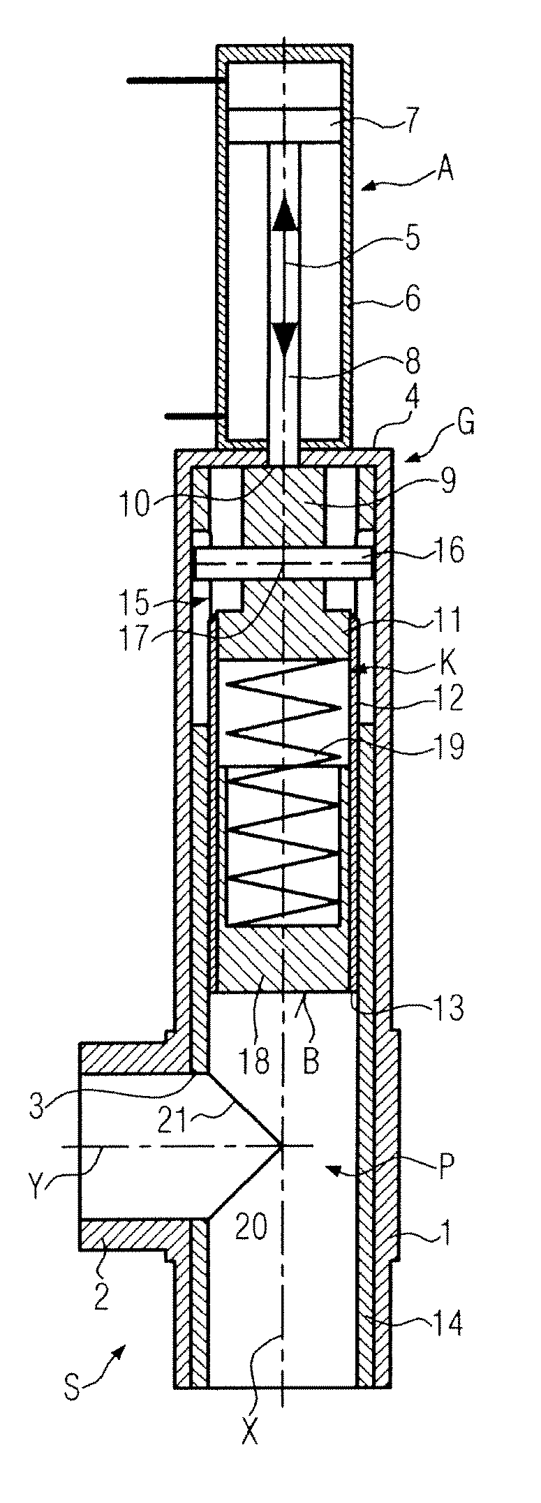
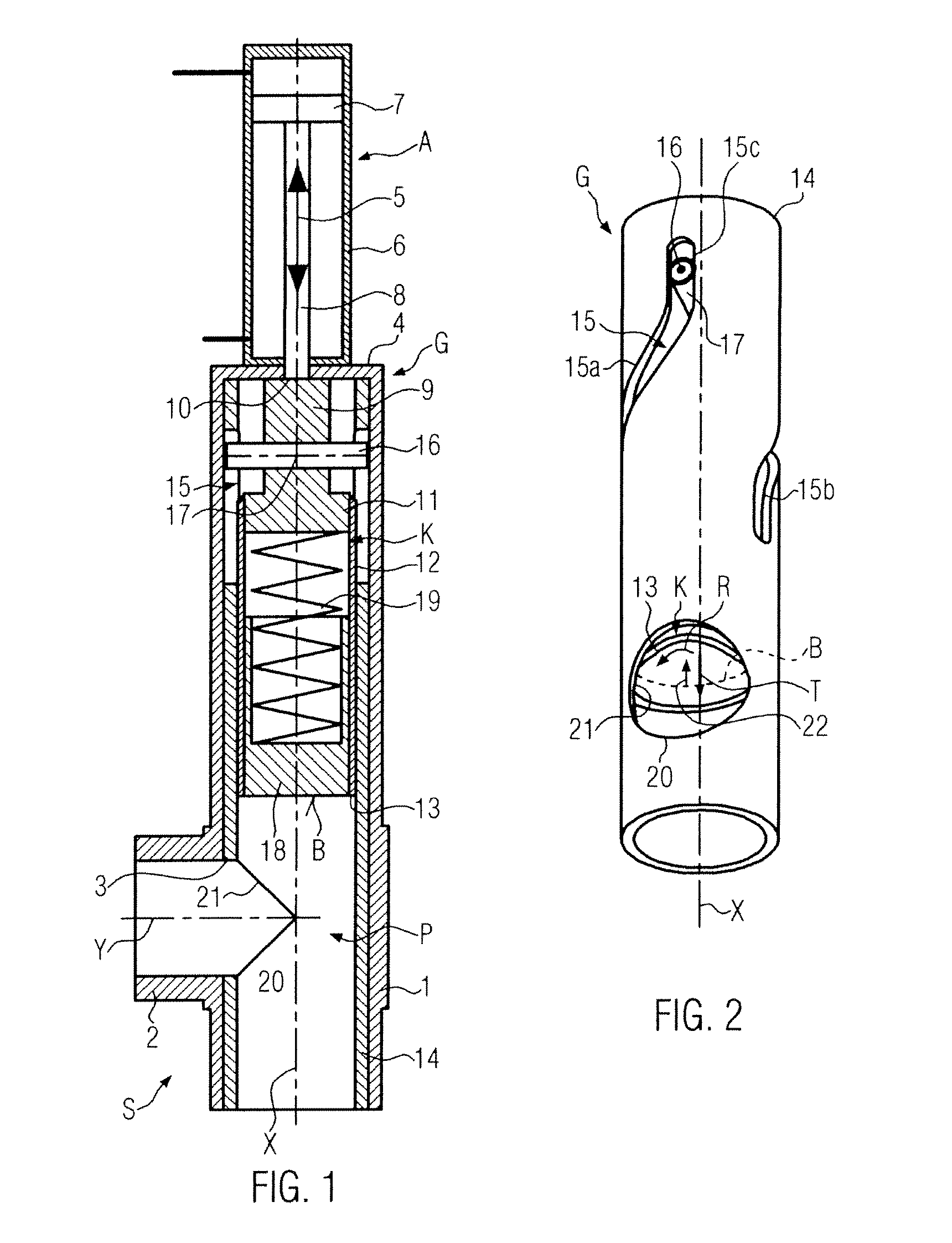
[0028]As shown in FIG. 1, in a cutting valve S for portioning a paste-like mass a portioning chamber P is contained in a cylinder 1 which is open at one end and comprises at least one lateral connecting pipe 2 which is connected to a storing and / or conveying unit (not shown) for the paste-like mass, e.g. a product of the food industry, e.g. sausage meat or ham or ham mass of lumpy or fibrous consistency. The connecting pipe 2 defines an inlet 3, here a lateral one, in the portioning chamber P. A mass strand from which the cutting valve S intermittently partitions portions and discharges the same, for instance by pushing them out, is supplied through the inlet 3.

[0029]The cylinder 1 has a bottom 4 with a passage opening for a piston rod 8 of a linear drive A, the housing 6 thereof being arranged on the bottom 4 or next thereto and containing a piston 7. The linear drive A is e.g. a compressed-air or hydraulic cylinder. As an alternative, an electromechanical spindle drive, or the lik...


PUM


Abstract

A cutting valve for portioning a paste-like mass, having a partitioning piston which is drivable in a portioning chamber with an inlet relative to the inlet and which comprises a cutting edge which during partitioning is movable to sweep over the inlet, the partitioning piston is drivable in the partitioning process to perform a helical movement with simultaneous translatory and rotatory movement components, so that the cutting edge carries out a draw cut in the mass strand.

Description

CROSS-REFERENCE TO RELATED APPLICATION[0001]The present application claims the benefit of priority of European Patent Application No. 09001826.8, filed Feb. 10, 2009. The entire text of the priority application is incorporated herein by reference in its entirety.FIELD OF THE DISCLOSURE[0002]The present disclosure relates to a cutting valve and to a method therefor.BACKGROUND[0003]In practice, cutting valves and portioning units, respectively, are known in the form of a cylinder with an axially movable piston. The mass strand is e.g. introduced via a lateral inlet into the cylinder before the partitioning piston partitions a portion by performing an axial movement and axially discharges the portion.[0004]As a rule, either volumetric portioning units or continuously intermittently working portioning units without any volumetric portioning operation are here concerned. In the volumetric portioning process the mass is filled under a specific pressure into the defined portioning chamber,...

Claims


Application Information

Patent Timeline
Patent Type & Authority Patents(United States)
IPC IPC(8): A22C11/04
CPCA22C11/04A22C11/06
Inventor MAILE, BERND
Owner ALBERT HANDTMANN MASCHFABRICK
Why Eureka
Try Eureka