Aircraft system modeling error and control error

Inactive Publication Date: 2012-10-09
NASA
View PDF12 Cites 43 Cited by
  • Summary
  • Abstract
  • Description
  • Claims
  • Application Information

AI Technical Summary

Benefits of technology

[0008]This invention presents a novel stable discrete-time adaptive law that is designed and implemented for flight control to targets damages/modeling errors in a direct adaptive control (DAC) framework. The approach is based on the observation that, where modeling errors are not present, the original control design has been tuned to achieve the desired performance. The adaptive control should, therefore, work towards achieving back this performance only when the design has modeling uncertainties/errors or when the vehicle suffers damage or substantial flight configuration change. In this work, the baseline controller uses dynamic inversion with proportional-integral augmentation. Dynamic inversion is carried out using the assumed system model. On-line adaptation of this control law is achieved by providing a parameterized augmentation signal to a dynamic inversion block. The parameters of this augmentation signal are updated to achieve the nominal desired error dynamics. Contrary to the typical Lyapunov-based adaptive approaches that guarantee only stability, the current approach investigates conditions for stability and for performance. A high-fidelity F-15 aircraft model is used to illustrate the overall approach.
[0009]Operationally, the aircraft plant dynamics is modeled, using the original plant description without changes, and the parameters representing the plant components are monitored. Under normal conditions, the controller responds to an excursion in the tracking error e(k), which is the difference between the desired and the actual aircraft behavior, and drives this tracking error toward a zero value according to n asymp

Problems solved by technology

If the tracking error does not conform to, or lie close to, this asymptotic curve, a resulting error (difference between desired error behavior and actual error behavior) is observed.

Method used


Image

  • Aircraft system modeling error and control error
  • Aircraft system modeling error and control error
  • Aircraft system modeling error and control error

Examples


Embodiment Construction

[0018]An adaptive controller, according to the invention, updates the nominal baseline control approach only if there is a modeling error or damage occurs or a substantial change in flight configuration occurs that cannot be corrected in a conventional manner by the controller.

Control Architecture.

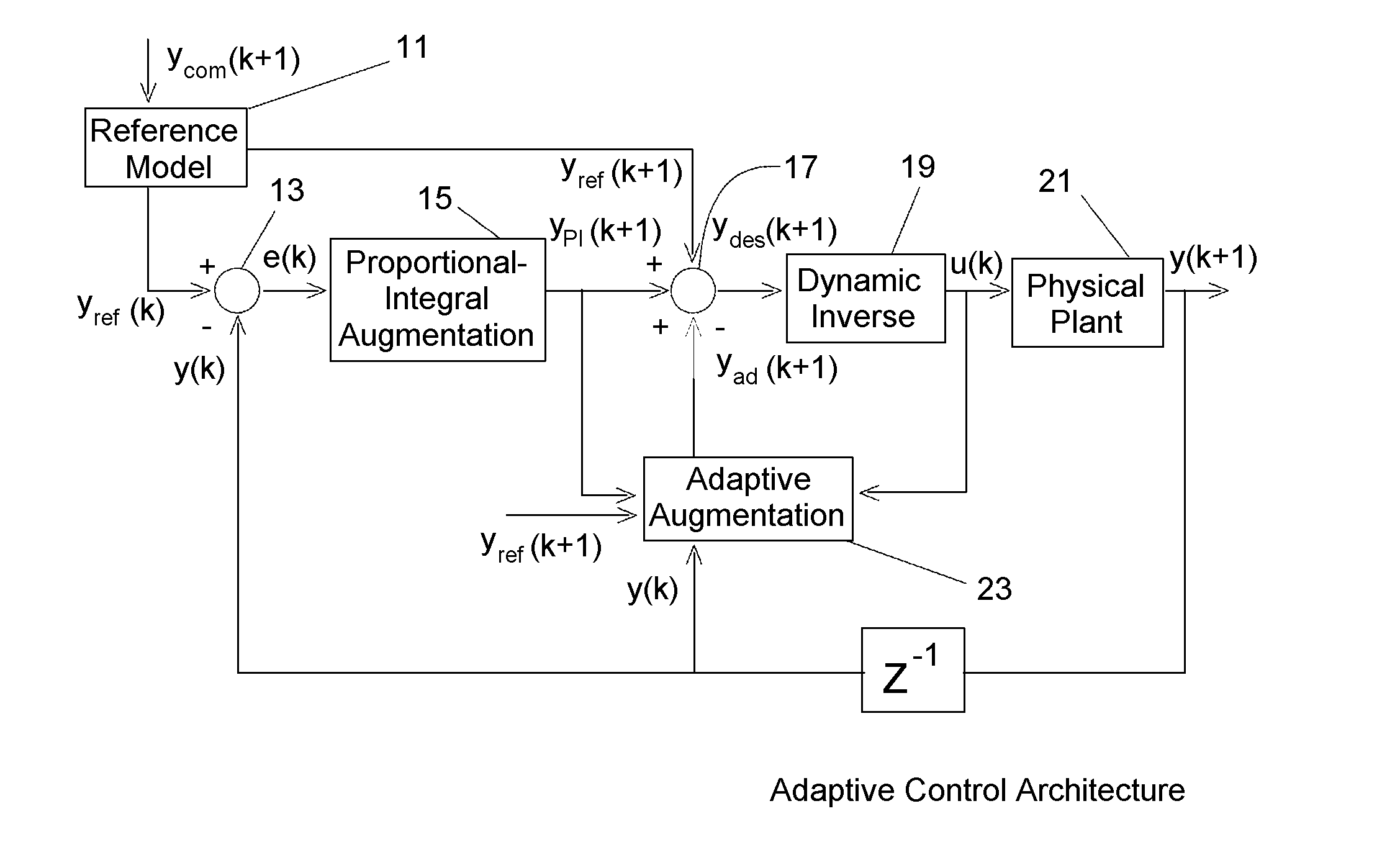
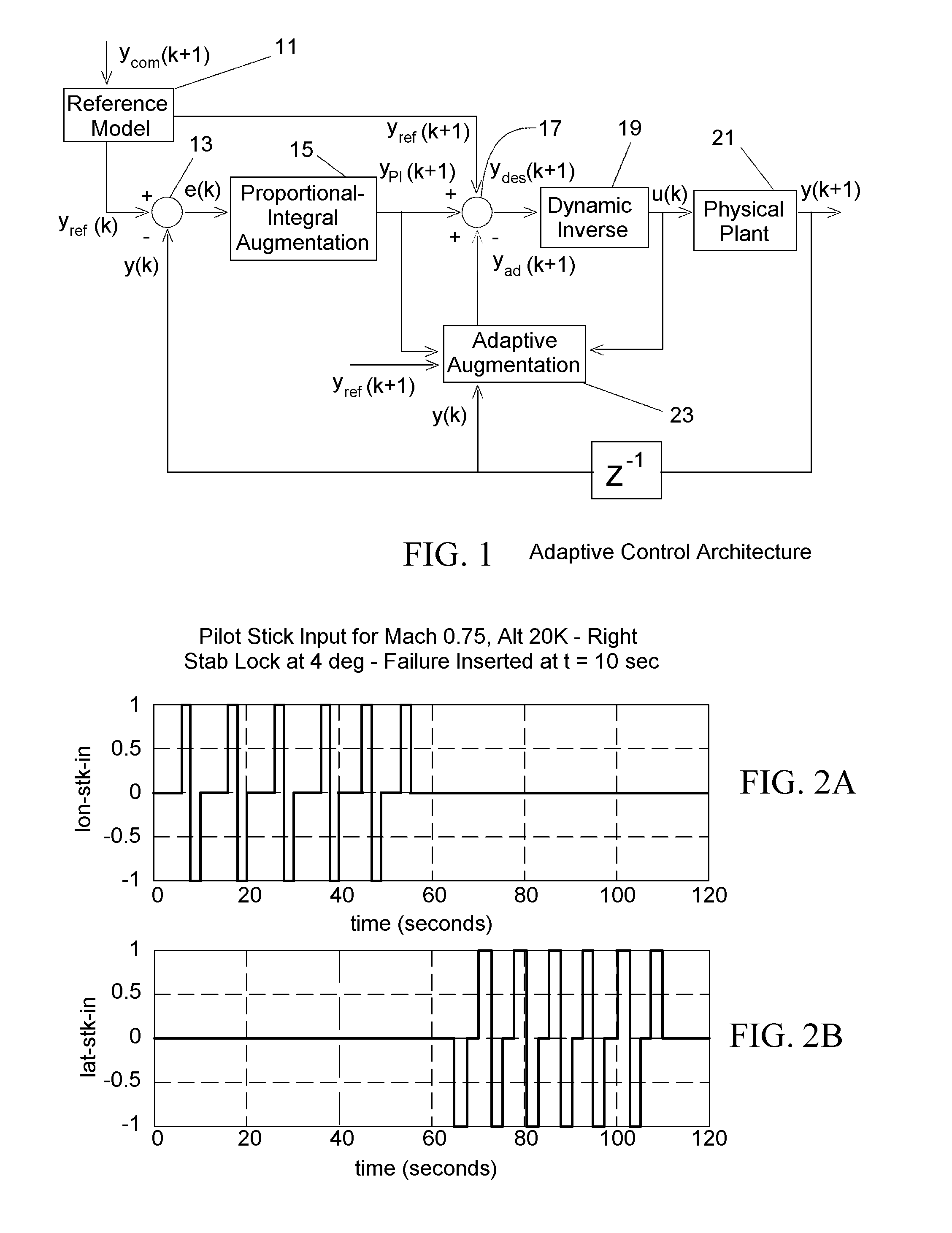
[0019]FIG. 1 presents the overall adaptive control architecture and schematically illustrates an embodiment of adaptive control architecture for practicing the invention. A reference module 11 provides a vector yref(k+1) of one or more aircraft system variables that are to be monitored and controlled, where k is a monotonically increasing time index. The reference vector yref(k) is received at a first difference module 13 that forms a difference vector, yref(k)−y(k)=e(k) that represents an error vector between a presently sensed aircraft system vector y(k) and the reference vector yref(k), which becomes an input signal for a proportional integral augmentation (PIA) module 15. An output sig...


PUM


Abstract

A method for modeling error-driven adaptive control of an aircraft. Normal aircraft plant dynamics is modeled, using an original plant description in which a controller responds to a tracking error e(k) to drive the component to a normal reference value according to an asymptote curve. Where the system senses that (1) at least one aircraft plant component is experiencing an excursion and (2) the return of this component value toward its reference value is not proceeding according to the expected controller characteristics, neural network (NN) modeling of aircraft plant operation may be changed. However, if (1) is satisfied but the error component is returning toward its reference value according to expected controller characteristics, the NN will continue to model operation of the aircraft plant according to an original description.

Description

ORIGIN OF THE INVENTION[0001]This invention was made, in part, by one or more employees of the U.S. government. The U.S. government has the right to make, use and / or sell the invention described herein without payment of compensation, including but not limited to payment of royalties.FIELD OF THE INVENTION[0002]This invention relates to minimization of modeling error and control error for an aircraft system.BACKGROUND OF THE INVENTION[0003]If an aircraft / spacecraft vehicle encounters a failure (such as a jammed control surface or loss of a surface), most controllers cannot adapt to the failure and a crash may occur. In most cases, the vehicle has enough redundant actuation mechanisms to salvage the vehicle. Several airplane crashes have occurred in the past where the pilot is unable to control the damaged airplane due to the pilot's inability to learn to fly this altered aircraft configuration in the very short time available. The flight computer, however, may have the necessary inf...

Claims


Application Information

Patent Timeline
IPC IPC(8): G05B13/02
CPCG05B17/02G05D1/0825
Inventor KULKARNI, NILESH V.KANESHIGE, JOHN T.KRISHNAKUMAR, KALMANJE S.BURKEN, JOHN J.
Owner NASA
Why Eureka
Try Eureka