Hydrogen gas storage device

a technology of hydrogen gas and storage device, which is applied in the direction of lighting and heating apparatus, packaging goods, separation processes, etc., can solve the problems of increasing the weight of each cell, the inability to stably fix the cells, and the large amount of mh must be retained in the cells

Inactive Publication Date: 2012-10-16
TOYOTA JIDOSHA KK
View PDF19 Cites 45 Cited by
  • Summary
  • Abstract
  • Description
  • Claims
  • Application Information

AI Technical Summary

Benefits of technology

[0012]Accordingly, it is an objective of the present invention to provide a hydrogen gas storage device capable of applying necessary binding force to a plurality of tank modules, each of which retains MH, without applying great fastening force to fastening members.

Problems solved by technology

However, when the heat utilization system described in Patent Document 1 is employed as, for example, a hydrogen supply source of an electric vehicle having a fuel cell, a large amount of MH must be retained in the cells, and the weight of each cell increases.
As a result, the cells cannot be stably fixed if the cells are only supported by the partition wall.

Method used


Image

  • Hydrogen gas storage device
  • Hydrogen gas storage device
  • Hydrogen gas storage device

Examples


Embodiment Construction

[0020]An embodiment of the present invention will now be described with reference to FIGS. 1 to 4.

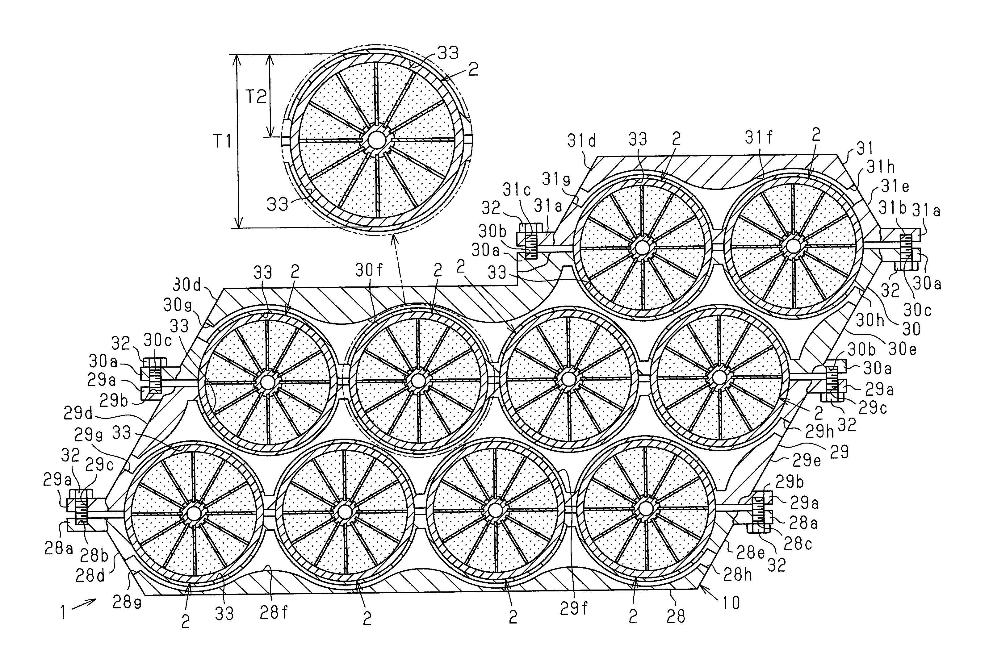
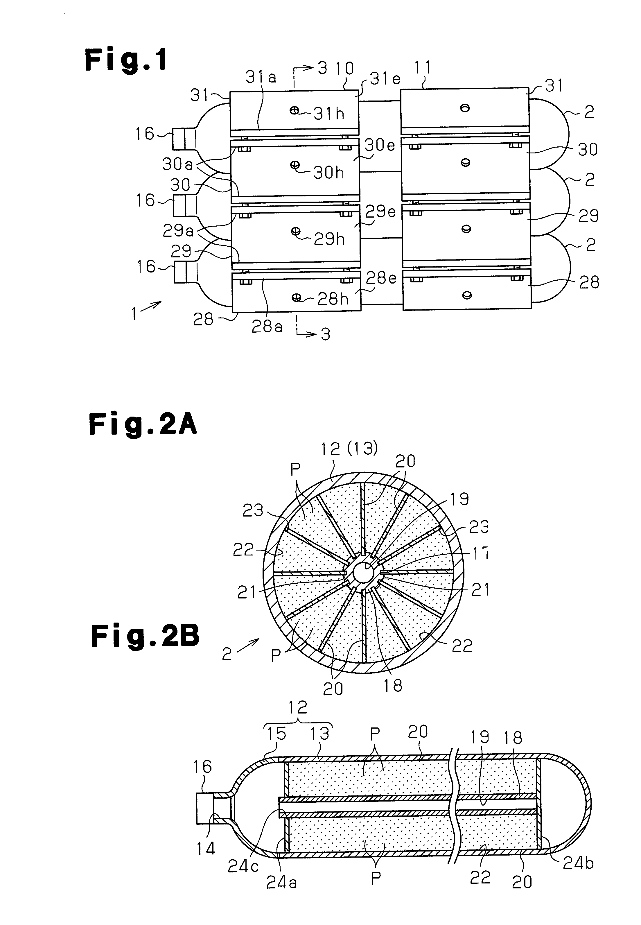
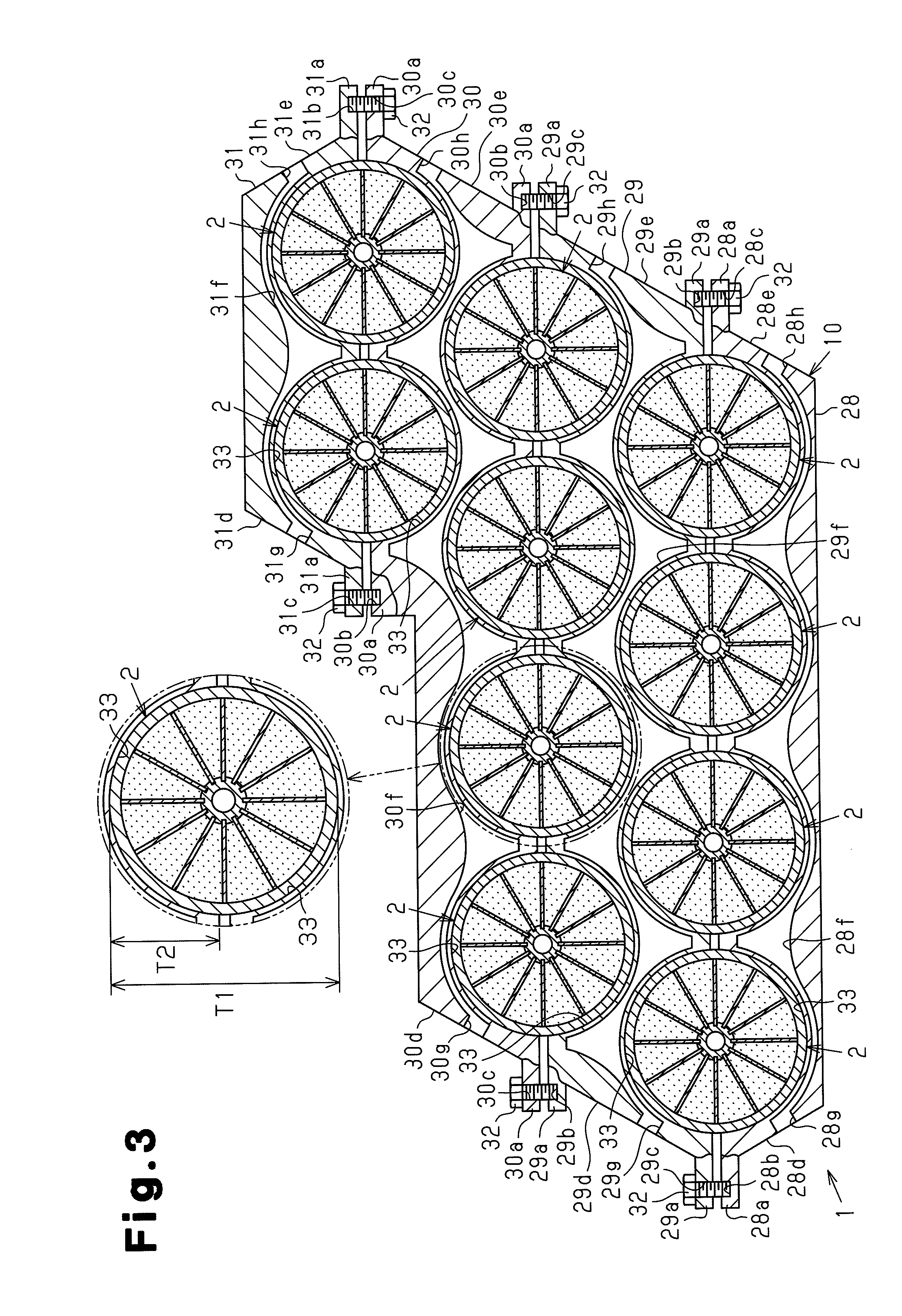
[0021]As shown in FIGS. 1 and 3, a hydrogen gas storage device 1 includes a plurality of (in the illustrated embodiment, ten) MH tank modules 2, which are stacked together while placed horizontally. The MH tank modules 2 are bound together by a first tank holder 10 and a second tank holder 11.

[0022]As illustrated in FIGS. 2A and 2B, each of the MH tank modules 2 substantially has an elongated columnar shape. Each MH tank module 2 is sized with the number of the MH tank modules 2 taken into consideration in such a manner that the MH tank module 2 is capable of supplying a sufficient amount of hydrogen to a hydrogen supply destination. The MH tank module 2 is formed of metal (for example, aluminum alloy) and has an outer shell portion 12, which has such a strength that the outer shell portion 12 tolerates sufficiently when the MH tank module 2 is filled with hydrogen and the pressure in t...


PUM

PropertyMeasurementUnit
pressureaaaaaaaaaa
lengthaaaaaaaaaa
lengthaaaaaaaaaa

Abstract

An MH tank module 2 has a hollow outer shell portion 12 formed of metal. The outer shell portion 12 has a plurality of MH powder retaining chambers 22 defined by a plurality of fins 20. A plurality of MH tank modules 2 are bound together by a first tank holder 10 and a second tank holder 11. The tank holders 10, 11 are each configured by fastening and fixing first, second, third, and fourth holder components 28-31, which are separate from one another. The first to fourth holder components 28-31 each have a heat medium passage 28f-31f. The first to fourth holder components 28-31 each have recessed portions 33 each corresponding to the shape of a side portion of each MH tank module 2. The MH tank modules 2 are held individually by the corresponding recessed portions 33.

Description

[0001]This application claims the benefit of International Application Number PCT / JP2008 / 060287, filed on Jun. 4, 2008 under 35 USC §371, entitled, “HYDROGEN GAS STORAGE DEVICE” which claims the benefit of Japanese Patent Application Number JP 2007-150987, filed on Jun. 6, 2007, all of which are hereby incorporated by reference.FIELD OF THE INVENTION[0002]The present invention relates to a hydrogen gas storage device configured by a plurality of tank modules in which hydrogen absorbing metal is retained.BACKGROUND OF THE INVENTION[0003]Using a hydrogen gas storage tank retaining powdered hydrogen absorbing metal (hereinafter, referred to as “MH”) as a hydrogen supply source of an electric vehicle having a fuel cell has been considered. The hydrogen gas storage tank stores the MH, which stores hydrogen, and supplies hydrogen to the hydrogen supply source by releasing the hydrogen from the MH. As one such type of hydrogen gas storage tank, a hydrogen gas storage tank having a heat med...

Claims


Application Information

Patent Timeline
Patent Type & Authority Patents(United States)
IPC IPC(8): B01D53/02F17C11/00
CPCF17C11/005H01M8/04208H01M8/04216H01M8/04029H01M8/065Y02E60/321Y02E60/50Y02E60/32
Inventor FUJITA, KATSUYOSHIKUBO, HIDEHITOMORI, DAIGOROHIROSE, KATSUHIKOHARAIKAWA, NORIHIKO
Owner TOYOTA JIDOSHA KK
Why Eureka
Try Eureka