Printable elastic composite

a technology of elastic composites and elastic strips, applied in the field of printing elastic strips, can solve the problems of reducing the surface area available for printing, irregular frequency and amplitude of pleats, and reducing print quality

Active Publication Date: 2012-10-16
KIMBERLY-CLARK WORLDWIDE INC
View PDF168 Cites 35 Cited by
  • Summary
  • Abstract
  • Description
  • Claims
  • Application Information

AI Technical Summary

Problems solved by technology

Although imparting elasticity to the composite, such pleats are often irregular in frequency and amplitude.
When attempting to print onto such an irregular surface, ink transfer may occur at both the “peaks” and “valleys” of the pleats, which reduces the surface area available for printing and thus reduces print quality.
While the small fiber size of meltblown facings can allow for some improvement in print quality, such facings normally possess insufficient durability for use in printing applications.

Method used


Image

  • Printable elastic composite
  • Printable elastic composite
  • Printable elastic composite

Examples


example

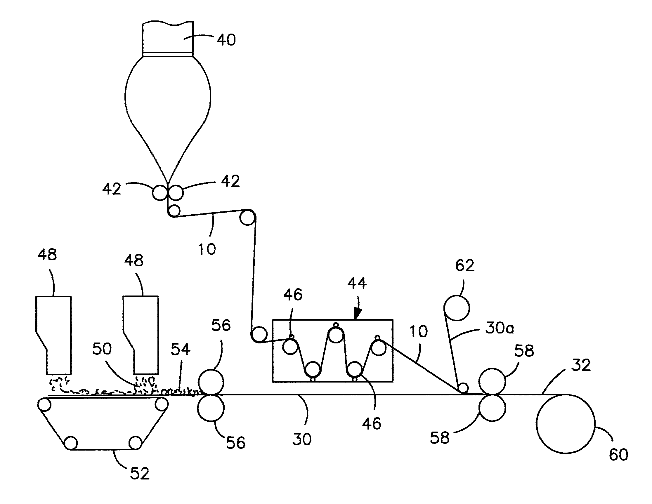
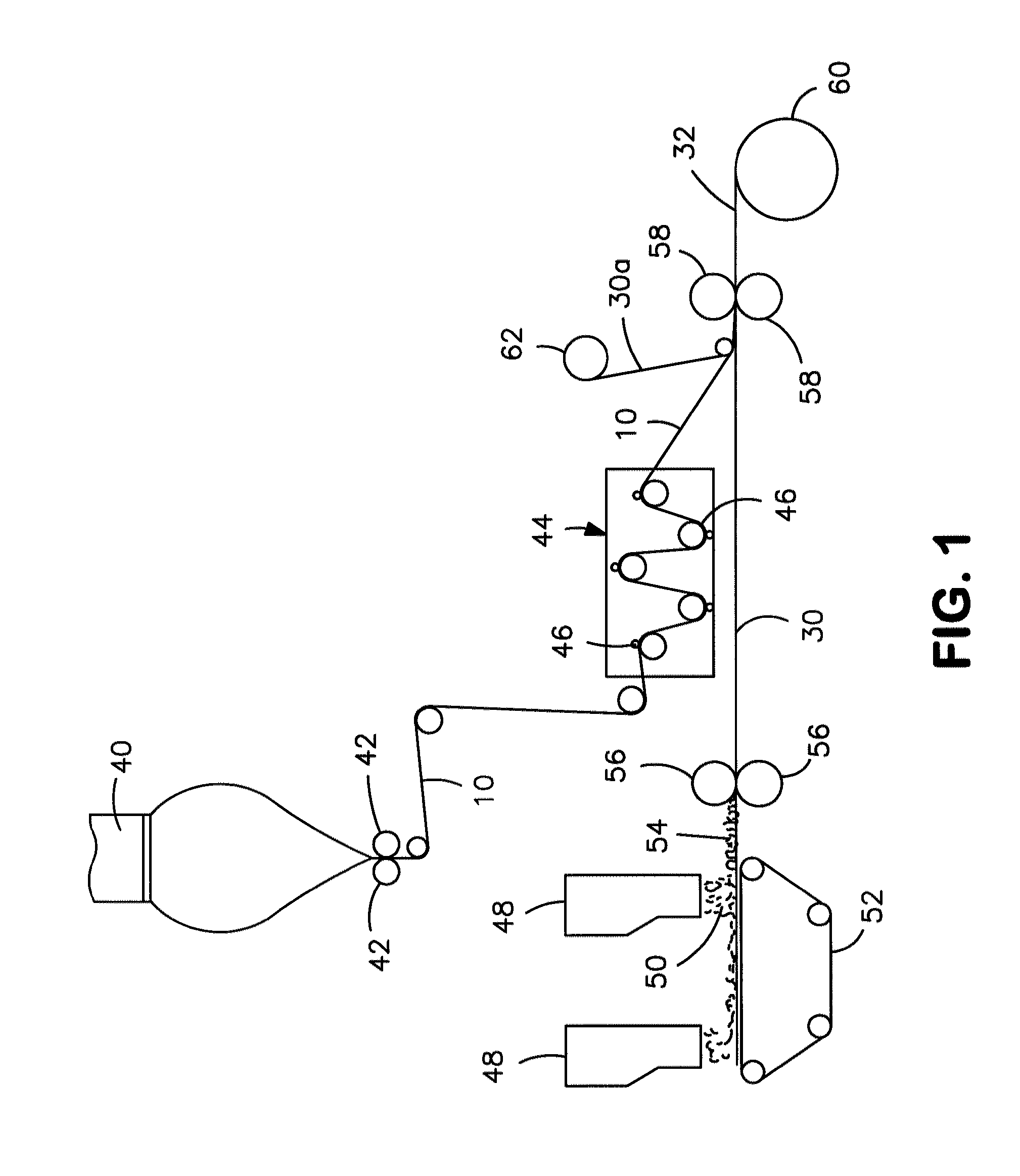
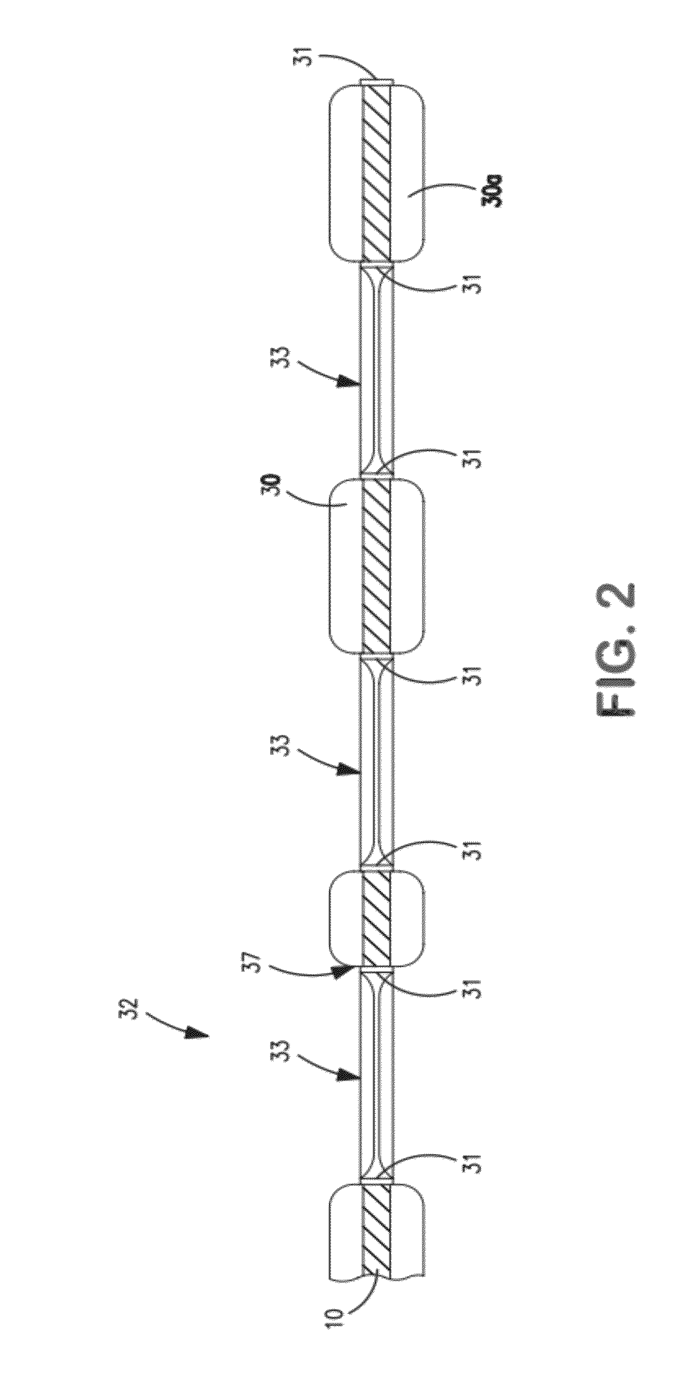
[0083]The ability to form a printable elastic composite in accordance with the present invention was demonstrated. The film of the composite was a single layer film composed of 98 wt. % VISTAMAXX™ 1100 and 2 wt. % titanium dioxide concentrate (TiO2 in polyethylene)available from Standridge Color Corp. under the designation “SCC 116921.” The film was cast at a speed of 50 ft / min on a primary casting roll, quenched, and transferred to a set of fixed S-wrap rollers operating at a speed of 50 ft / min. The film was then drawn under tension from the S-wrap to a thermal bonding calender stack at a draw ratio of 4.5× (225 ft / min at calender). The tensioned film was combined in the calender stack nip with a meltblown facing (upper side) and a spunbond facing (lower side), both of which were unwound at a speed of 225 ft / min. The spunbond facing had a basis weight of 13.6 gsm and was composed of 98 wt. % polypropylene (STF 315, ExxonMobil) and 2 wt. % TiO2. The meltblown facing had a basis weig...


PUM

PropertyMeasurementUnit
temperatureaaaaaaaaaa
diameteraaaaaaaaaa
diametersaaaaaaaaaa

Abstract

A composite that contains an elastic film laminated to a meltblown facing is provided. During lamination, apertures and discrete bond sites may be concurrently formed in the elastic film. The discrete bond sites may be located proximate (adjacent or near to) a perimeter defined by corresponding apertures formed by displacement of the film. The location of the bond sites adjacent to or near the apertures may enhance the durability of the meltblown facing by strengthening the area surrounding the apertures. Furthermore, the content of the elastic film and the temperature / pressure of lamination may be selected to that the film possesses a sufficient tack for adhering to the facing at regions other than those fused together by the bonding elements of the patterned roll. Such secondary bonding further stabilizes the meltblown facing and renders it suitable for printing. Further, the film is under tension in the machine direction during lamination. Subsequent to lamination, however, the film is retracted so that the facing retracts toward its original machine direction length, thereby gathering and forming pleats. It has been discovered that these pleats have a relatively small amplitude (height), as well as a substantially uniform frequency across the surface of the facing. Such a small height and increased regularity improves the ability to transfer an ink to “peaks” of the pleats, thereby improving print quality and uniformity.

Description

BACKGROUND OF THE INVENTION[0001]Elastic composites are commonly incorporated into products (e.g., diapers, training pants, garments, etc.) to improve their ability to better fit the contours of the body. For example, the elastic composite may be formed from an elastic film and a nonwoven facing. The nonwoven facing may be joined to the elastic film while the film is in a stretched condition so that the nonwoven facing can gather and form “pleats” between the locations where it is bonded to the film when it is retracted. The resulting elastic composite is stretchable to the extent that the pleats allow the elastic film to elongate. Although imparting elasticity to the composite, such pleats are often irregular in frequency and amplitude. When attempting to print onto such an irregular surface, ink transfer may occur at both the “peaks” and “valleys” of the pleats, which reduces the surface area available for printing and thus reduces print quality. While the small fiber size of melt...

Claims


Application Information

Patent Timeline
Patent Type & Authority Patents(United States)
IPC IPC(8): B32B37/00
CPCB32B37/144B41M5/0047B41M5/0064B32B37/0076B32B38/145B32B2305/20Y10T428/24281B32B2307/75Y10T156/1056B32B2307/51B29C55/02B29C59/02B41M5/00
Inventor LAKE, MATTHEW B.FITTS, JR., JAMES R.
Owner KIMBERLY-CLARK WORLDWIDE INC
Why Eureka
Try Eureka