Drawer type cooking device

a cooking device and drawer body technology, applied in the field of cooking devices, can solve the problems of difficult power supply and signal transmission between the control unit disposed in the cooking device body and the operation unit of the cooking device body moved to open and close with respect to the cooking device body, difficult power supply from the power supply unit disposed on the cooking device body to the illumination device, and relatively expensive cables. , to achieve the effect of low cost components, easy operation and low cos

Active Publication Date: 2012-10-23
SHARP KK
View PDF18 Cites 20 Cited by
  • Summary
  • Abstract
  • Description
  • Claims
  • Application Information

AI Technical Summary

Benefits of technology

[0023]Therefore, in order to supply power and transmit signals between the cooking device body and the drawer body, it is common to provide connection via a bendable lead wire such as a flexible cable, but such cables are relatively expensive, and the durability of the lead wire becomes a problem with respect to the repeated opening and closing operation of the drawer body. Therefore, one problem to be solved is to supply power and transmit signals between a cooking device body and a drawer body movable with respect to the cooking device body and having an operation unit disposed thereon using an existing mechanism, and realizing superior durability.
[0034]Further according to the present drawer type cooking device, since the power supply from the cooking device body to the illumination device disposed on the drawer body is realized via existing movement mechanisms disposed on the exterior of the heating chamber, the present cooking device utilizes the existing movement mechanisms on the drawer body and the cooking device body that realize a slidable state providing constant conduction as power supply path without providing additional components, so that the power supply to the illumination device can be performed at a low cost. Moreover, since there is no need to use bendable lead wires, durability is exerted even after repeated opening and closing operation of the drawer body, since the present arrangement does not adopt lead wires liable to disconnection of signal wire caused by the opening and closing operation of the door. Further, the present arrangement is rarely influenced by the microwaves used for heating and cooking. Moreover, since the illumination device of the cooking device can be disposed on the drawer body and not on the cooking device body, the illumination device can illuminate the interior of the drawer body even after the drawer body is drawn out. Further, if an LED is used as solid light source of the illumination device, there is no drawback of filament damage as in incandescent lamps, and there is extremely small possibility of damage and failure being caused by the impact accompanying the opening and closing of the door. Another advantage of disposing the illumination device on the door is that the replacement of the light source when failure occurs is facilitated.

Problems solved by technology

Therefore, if it is possible to arrange the operation unit on the upper portion of the door of the drawer body, the reduced ceiling height of the drawer body caused by disposing the operation unit on the upper portion of the cooking device body can be solved, but such arrangement has a drawback in that the power supply and signal transmission between the control unit disposed in the cooking device body and the operation unit of the drawer body moved to open and close with respect to the cooking device body becomes difficult.
However, this arrangement has a drawback in that the power supply from the power supply unit disposed on the cooking device body to the illumination device moved together with the drawer body that moves in opening and closing operation with respect to the cooking device body becomes difficult.
Therefore, in order to supply power and transmit signals between the cooking device body and the drawer body, it is common to provide connection via a bendable lead wire such as a flexible cable, but such cables are relatively expensive, and the durability of the lead wire becomes a problem with respect to the repeated opening and closing operation of the drawer body.
However, such cables are relatively expensive, and the lead wires are subjected to bending motion for a number of times corresponding to the number of times the door is opened and closed with the movement of the drawer body, by which the lead wires are liable to disconnection.
Since power supply via lead wires is extremely disadvantageous from the viewpoint of durability, it is very difficult to put such arrangement into practice.

Method used


Image

  • Drawer type cooking device
  • Drawer type cooking device
  • Drawer type cooking device

Examples


Embodiment Construction

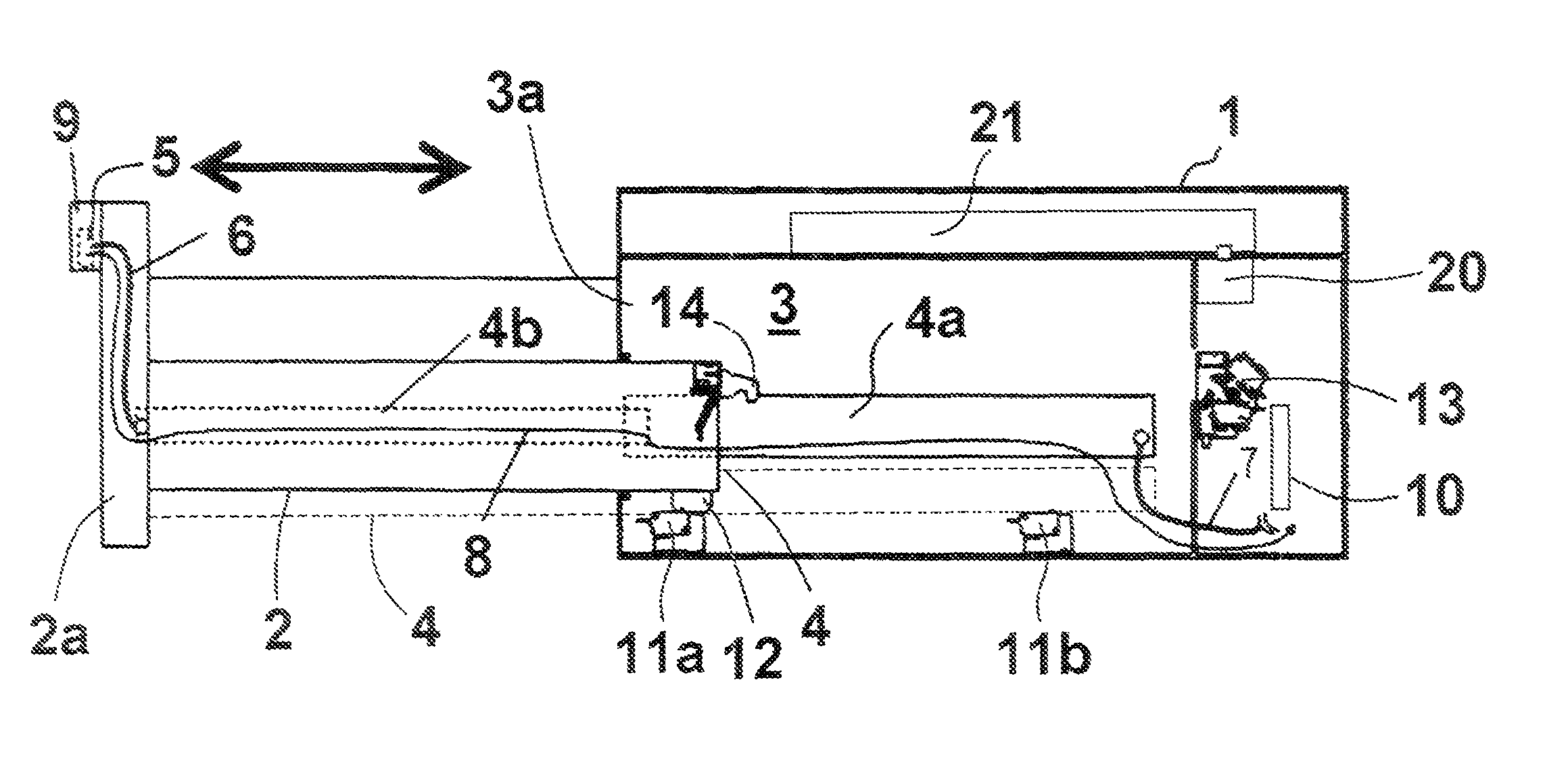
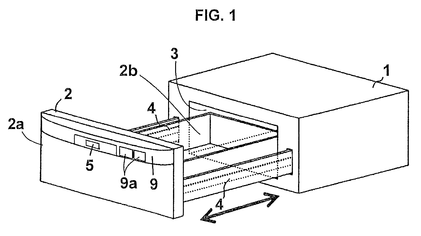
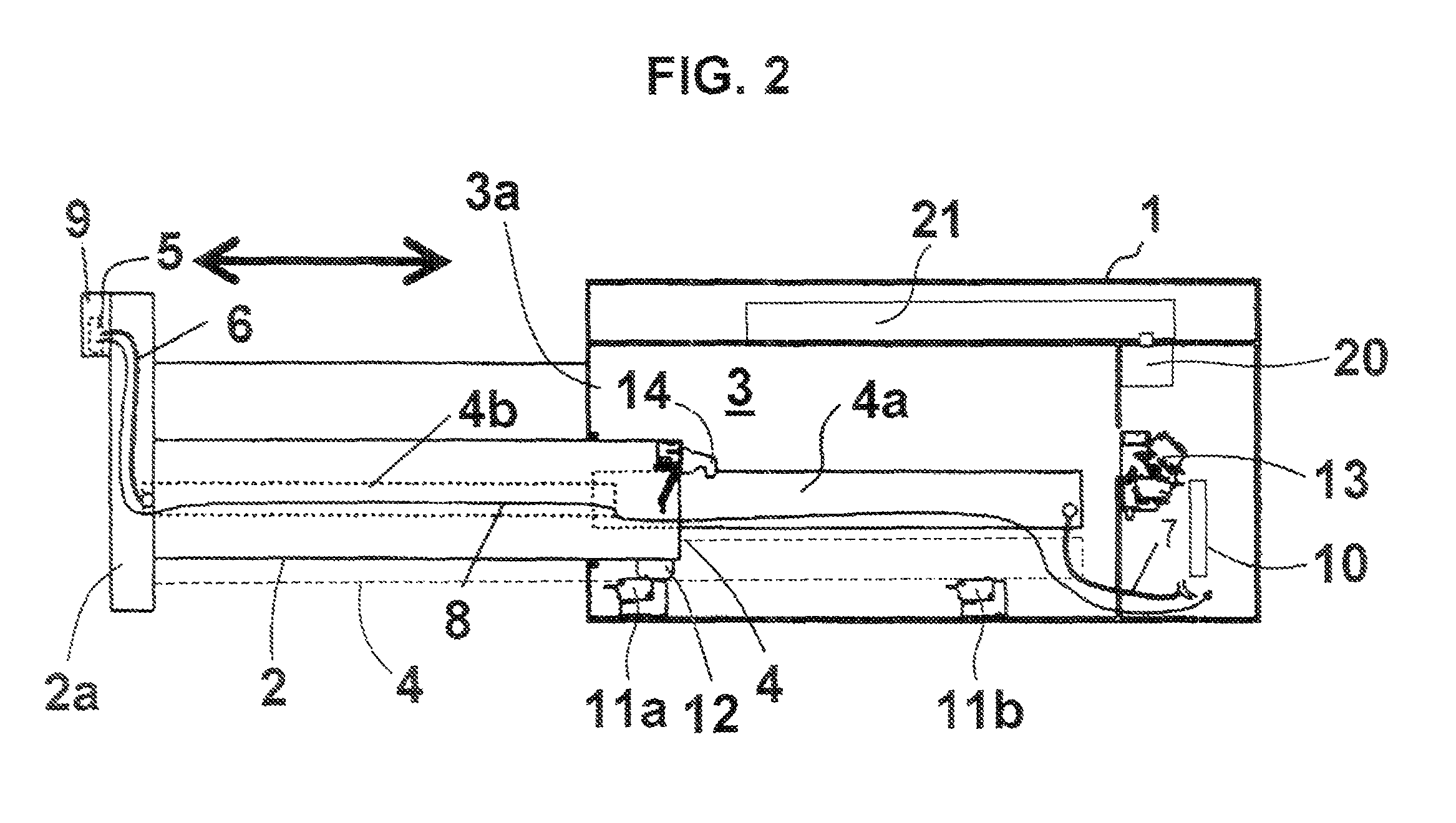
[0041]Now, the preferred embodiments of a drawer type cooking device according to the present invention will be described with reference to the drawings. FIG. 1 is a perspective view showing the overall exterior of the drawer type cooking device according to one embodiment of the present invention. FIG. 2 is a partially cutaway side view of the drawer type cooking device illustrated in FIG. 1.

[0042]As illustrated in FIG. 1, the drawer type cooking device (hereinafter referred to as cooking device) comprises a cooking device body 1 and a drawer body 2 capable of being drawn out of the cooking device body 1. In the interior of the cooking device body 1 is formed a heating chamber 3 for heating an object to be heated loaded on the drawer body 2. On the front side of the cooking device body 1 is formed an opening 3a enabling the drawer body 2 to be drawn out of the heating chamber 3.

[0043]The drawer body 2 comprises a door 2a for opening and closing the heating chamber 3, and a containe...


PUM


Abstract

The invention provides a drawer type cooking device having an operation unit disposed on an upper portion of a drawer body so as to increase the height of the drawer body within a cooking device body as much as possible, capable of facilitating power supply and signal transmission between the control unit within the cooking device body and the operation unit when the drawer body is opened and closed. Slide mechanisms 4 disposed on left, right and bottom portions enabling the drawer body 2 to be moved into and out of the cooking device body 1 are composed of conductive materials, so as to provide a slidable state with constant conduction. By transmitting data via serial communication and supplying power to the operation unit from the cooking device body 1 to the drawer body 2, it becomes possible to dispose the operation unit on a door 2a being opened and closed. By forming the operation unit including a microcomputer for communication on the drawer body 2, it becomes possible to increase the ceiling height of the drawer body 2, increase the ceiling height and capacity of the heating chamber 3, and enlarge the height limitation of an object to be cooked. An illuminating light source 25 disposed on the door 2a of the drawer body 2 can also receive power supply via the arrangement described above to illuminate food loaded in the drawer body 2.

Description

[0001]The present application is based on and claims priority of Japanese patent applications No. 2008-146722 filed on Jun. 4, 2008 and No. 2008-146723 filed on Jun. 4, 2008, the entire contents of which are hereby incorporated by reference.BACKGROUND OF THE INVENTION[0002]1. Field of the Invention[0003]The present invention generally relates to cooking devices, and more specifically, relates to drawer-type cooking devices in which a drawer body storing or loading therein an object to be cooked is placed in the interior of the cooking device body and capable of being drawn out therefrom.[0004]2. Description of the Related Art[0005]In a drawer type cooking device built into a kitchen unit, the size of the opening of a heating chamber disposed on a front side of the cooking device body is factually standardized into a few designs, and therefore, the width, depth and height of the built-in cooking device must satisfy determined sizes. For example, the cooking device that the present ap...

Claims


Application Information

Patent Timeline
Patent Type & Authority Patents(United States)
IPC IPC(8): A21B1/40H05B6/80A47B81/00
CPCA47J39/00F24C15/162
Inventor IWAMOTO, MASAYUKIKISHIMOTO, MASAMITSU
Owner SHARP KK
Why Eureka
Try Eureka