Pressure control in low static leak fuel system

a fuel system and static leakage technology, applied in the direction of electrical control, process and machine control, instruments, etc., can solve the problems of increasing the reduction rate, or decay rate, the pressure within, and the pressure may not be reduced at the desired rate,

Inactive Publication Date: 2012-10-23
CATERPILLAR INC
View PDF40 Cites 62 Cited by
  • Summary
  • Abstract
  • Description
  • Claims
  • Application Information

AI Technical Summary

Problems solved by technology

However, the lack of static leakage from the fuel system may present a previously unrecognized performance challenge, such that when a reduction in rail pressure is required, the pressure may not be reduced at a desired rate.
More specifically, conventionally designed fuel systems, which may allow a tolerable amount of leakage, may increase a reduction rate, or decay rate, of pressure within the rail, whereas the low static leak fuel system may not.
As a result, for example, the settle time required for an operational engine having a low static leak fuel system to go from a high load condition, during which relatively high rail pressures are used, to a low load or idle condition, during which relatively low rail pressures are used, may be compromised.
While the reference may effectively reduce or prevent over-pressurization from occurring, it does not recognize a need for controlling rail pressure in low static leak fuel systems.

Method used


Image

  • Pressure control in low static leak fuel system
  • Pressure control in low static leak fuel system
  • Pressure control in low static leak fuel system

Examples


Embodiment Construction

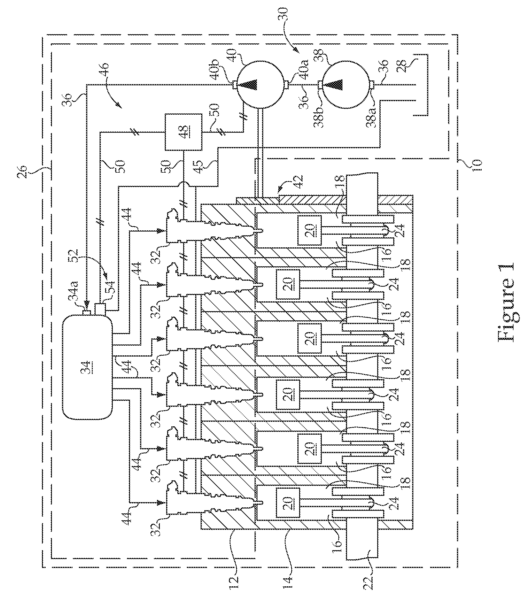
[0018]Referring to FIG. 1, an engine system 10 may generally include an internal combustion engine 12, such as a compression ignition engine. The internal combustion engine 12 may include an engine block 14 that defines a plurality of cylinders 16, each of which forms a combustion chamber 18. A piston 20 is slidable within each cylinder 16 to compress air within the respective combustion chamber 18. The internal combustion engine 10 also includes a crankshaft 22 that is rotatably disposed within the engine block 14. A connecting rod 24 may connect each piston 20 with the crankshaft 22 such that sliding motion of the pistons 20 within each respective cylinder 16 results in a rotation of the crankshaft 22. Similarly, rotation of the crankshaft 22 may result in linear sliding motion of the pistons 20.

[0019]The engine system 10 may also include a low static leak fuel system 26, also referred to as a common rail fuel system, for supplying fuel into each of the combustion chambers 18 dini...


PUM


Abstract

A pressure relief valve includes a valve body having a valve seat fluidly positioned between an inlet and an outlet. A valve member is movable among a first position, a second position, and a third position. The valve member is in contact with the valve seat and fluidly blocks the inlet from the outlet at the first position. At the second position of the valve member, the inlet is fluidly connected to the outlet via a small flow area. The inlet is fluidly connected to the outlet via a large flow area when the valve member is at the third position. An electrical actuator is attached to the valve body and is operably coupled to move the valve member when energized. The valve member includes an opening hydraulic surface exposed to fluid pressure in the inlet when at the first position. A spring is operably positioned to bias the valve member toward the second position when the valve member is at the third position.

Description

TECHNICAL FIELD[0001]The present disclosure relates generally to pressure control in common rail fuel systems, and more particularly to a means for controlling rail pressure in low static leak fuel systems.BACKGROUND[0002]Common rail fuel systems typically include a fuel source and fuel delivery components for supplying fuel directly into cylinders of an internal combustion engine by way of a common rail. Fuel within the common rail may be pressurized to a relatively high pressure using one or more pumps, and may be delivered to fuel injectors through a plurality of individual fuel supply passages. A control system may be associated with the fuel system to monitor and control operation of one or more of the fuel system components. Specifically, for example, the control system may be configured to control the high-pressure pump and each of the fuel injectors to control pressurization rates and injection, thus improving performance and control of the engine. Typically, such fuel syste...

Claims


Application Information

Patent Timeline
Patent Type & Authority Patents(United States)
IPC IPC(8): F02M59/36
CPCF02D41/3863F02M63/0052F02M63/0054F02M63/025F02D41/042F02D41/062
Inventor SHAFER, SCOTT F.DEPAYVA, JEFFREYPUCKETT, DANIEL R.JOHANSON, AMY S.ADAMS, KENNETH C.TOWER, BENJAMIN R.LI, JASON Z.VENKATARAGHAVAN, JAYARAMANGERSTNER, MICHAEL D.LONG, MICHAEL C.
Owner CATERPILLAR INC
Why Eureka
Try Eureka