Hypersonic inlet systems and methods

a technology of hypersonic inlet and inlet, which is applied in the direction of efficient propulsion technologies, machines/engines, instruments, etc., can solve the problems that the plane variable geometry features (e.g., flat flaps with effective sealing) have not been effectively integrated with the inlet, and achieve the effect of adequate pressure recovery and sufficient operability margin

Active Publication Date: 2012-10-23
ORBITAL ATK INC +1
View PDF3 Cites 22 Cited by
  • Summary
  • Abstract
  • Description
  • Claims
  • Application Information

AI Technical Summary

Benefits of technology

[0007]The present invention is directed to hypersonic inlet systems and methods. Embodiments of the present invention may advantageously provide desired inlet capabilities, including supplying the required amount of air with adequate pressure recovery and sufficient operability margin for each propulsion system independently, and also during propulsion system transition from low-speed to high-speed operating mode, without a great deal of mechanical complexity.

Problems solved by technology

Typically, planar variable geometry features (e.g., flat flaps with effective sealing) have not been effectively integrated with inlets which are defined by axisymmetric flowfields.

Method used


Image

  • Hypersonic inlet systems and methods
  • Hypersonic inlet systems and methods
  • Hypersonic inlet systems and methods

Examples


Embodiment Construction

[0018]The present invention relates to hypersonic inlet systems and methods. Many specific details of certain embodiments of the invention are set forth in the following description and in FIGS. 1-6 to provide a thorough understanding of such embodiments. The present invention, however, may have additional embodiments, or may be practiced without one or more of the details described below.

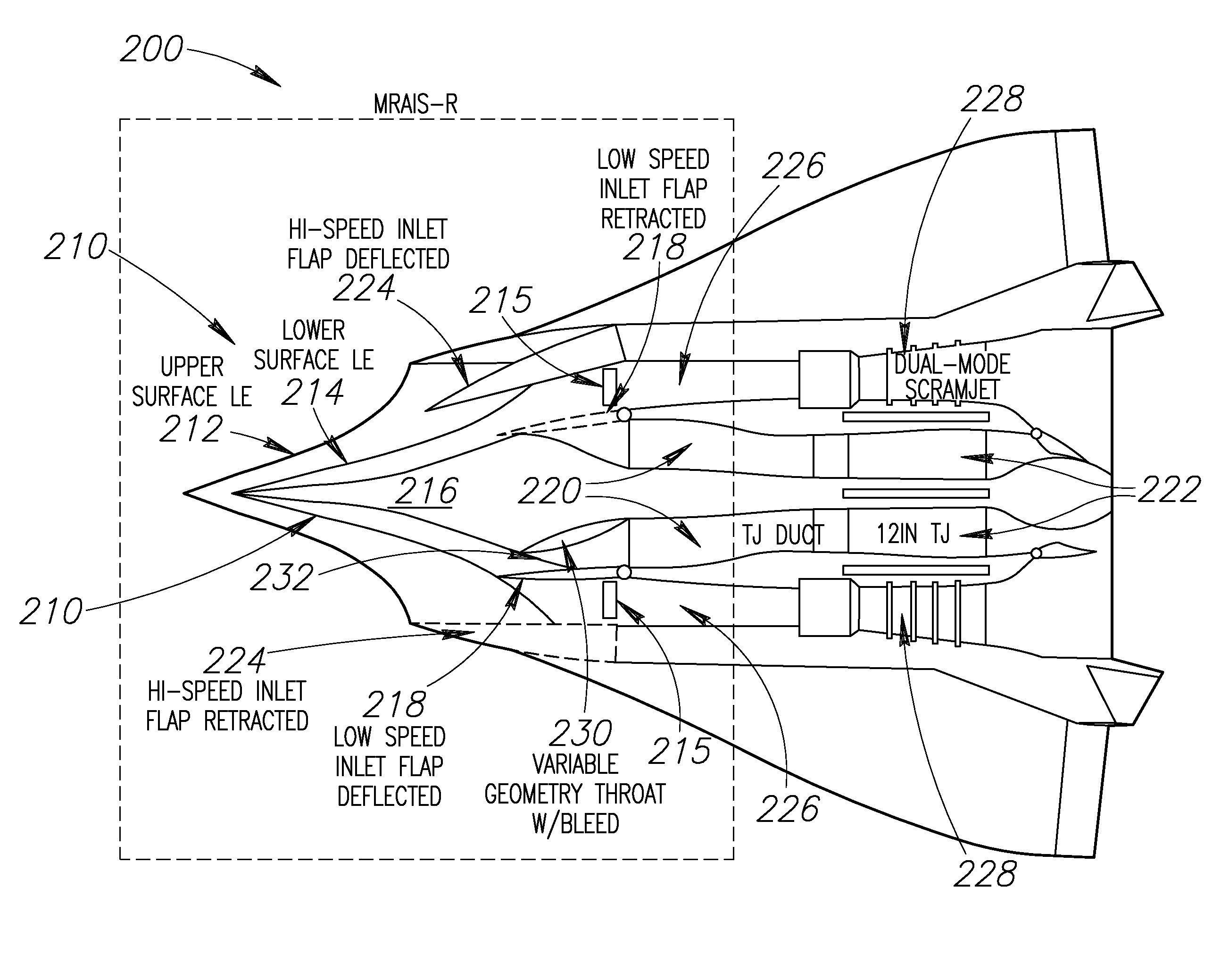
[0019]As described above, prior art turbine-based combined cycle (TBCC) inlets have traditionally relied upon a more purely planar (or two-dimensional 2D) geometry as integrated into an over / under arrangement, with the turbine flowpath being above the ramjet / scramjet flowpath. Also, the prior art approach generally had the turbine inlets external to, and forward of, the ramjet / scramjet inlet, while sharing a common external forebody, which facilitated incorporation of planar variable geometry.

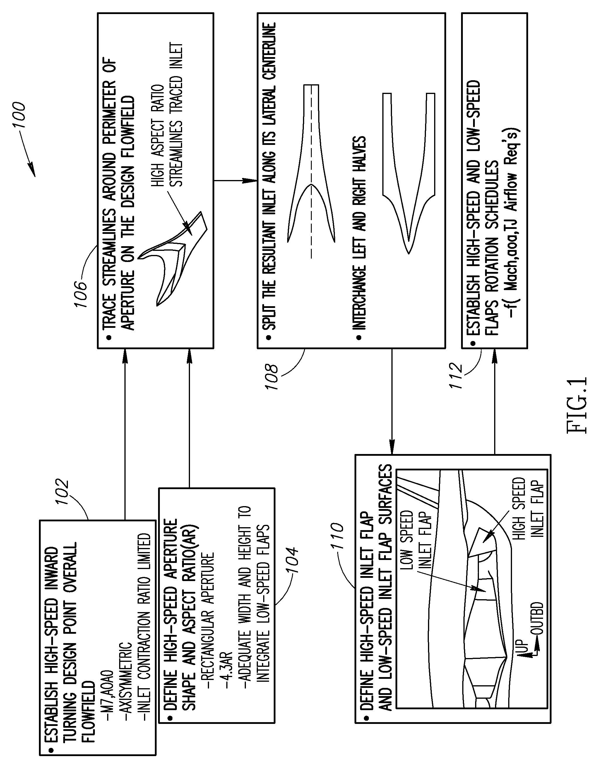
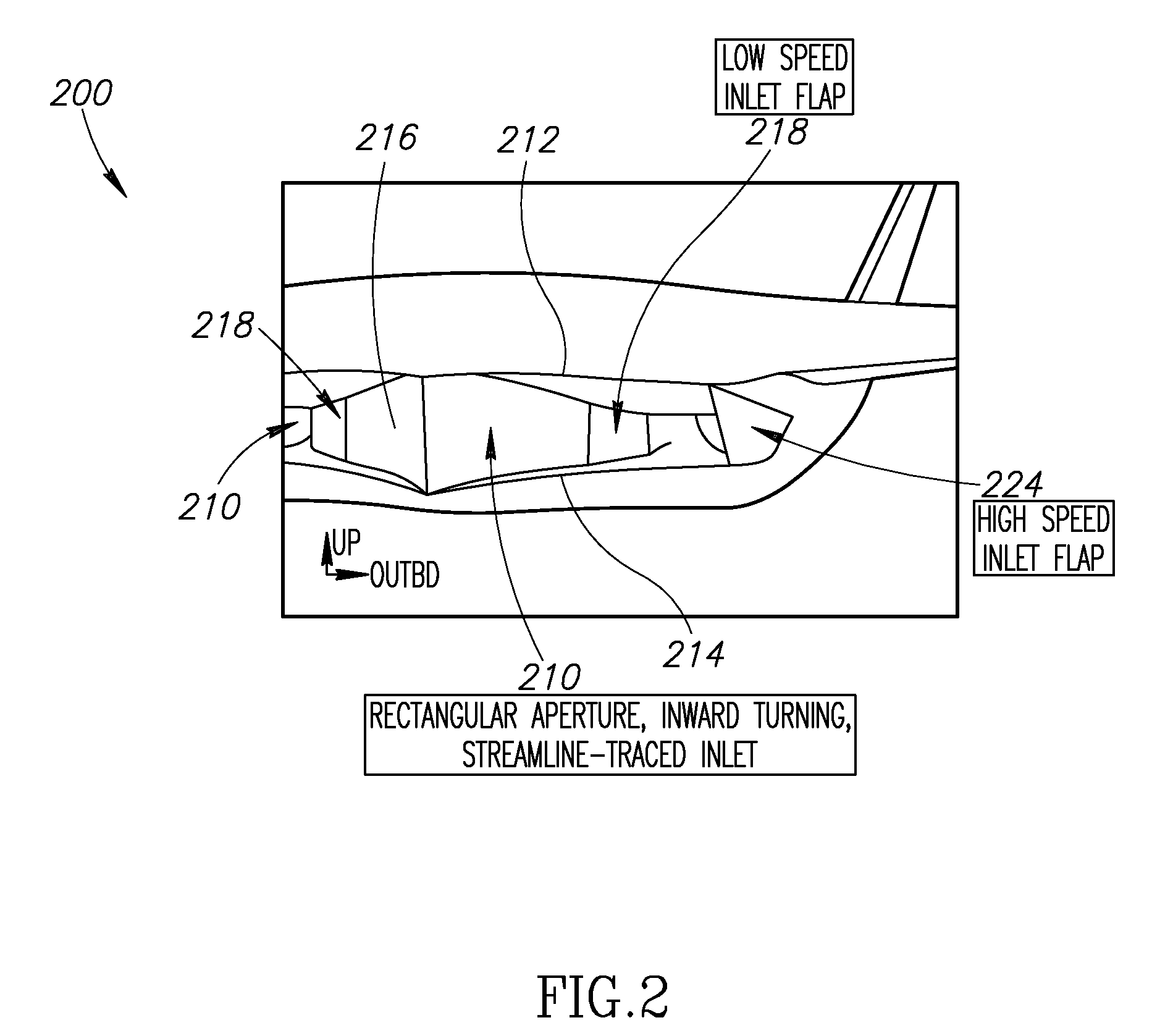
[0020]In general, embodiments of the present invention anchor to a potentially higher-performing streamline...


PUM


Abstract

Hypersonic inlet systems and methods are disclosed. In one embodiment, an inlet for an airbreathing propulsion system includes an inboard surface at least partially shaped to conform to a plurality of streamline-traces of a design flowfield approaching an aperture, an outboard surface spaced apart from the inboard surface, an upper surface extending between the inboard and outboard surfaces, and a lower surface extending between the inboard and outboard surfaces, wherein leading edges of the inboard, outboard, upper, and lower surfaces cooperatively define the aperture.

Description

CROSS-REFERENCE TO RELATED APPLICATIONS[0001]This application claims priority benefit from U.S. Provisional Patent Application No. 60 / 942,186, filed on Jun. 5, 2007, entitled “HYPERSONIC INLET SYSTEMS AND METHODS”.STATEMENT OF GOVERNMENT INTEREST[0002]This invention was made with government support under subcontract number G1103-0002 to U.S. Government Contract NNL04AA01C awarded by the National Aeronautics and Space Administration. The U.S. Government has certain rights in this invention.FIELD OF THE INVENTION[0003]The present disclosure relates to airbreathing propulsion systems, and more specifically, to hypersonic inlet systems and methods.BACKGROUND OF THE INVENTION[0004]In order to operate efficiently, airbreathing hypersonic vehicles generally rely on at least two propulsion system types to complete their missions: one to propel the vehicle at relatively low speeds (Mach 0 to 3-4), and one to take over at higher speeds (Mach 3-4 to Mach 7-9 for hydrocarbon-fueled accelerator ...

Claims


Application Information

Patent Timeline
Patent Type & Authority Patents(United States)
IPC IPC(8): B64D33/02F02K7/10F02K7/08
CPCB64C30/00B64D33/02F02C7/042F02K7/10G06F17/5095B64D2033/026Y02T50/67F05D2220/80G06F30/15Y02T50/60
Inventor SMITH, THOMAS R.ESPINOSA, ANGEL M.FARRELL, DANIEL J.ROBERTSON, ANDREWLEYLEGIAN, JOHN C.TYLL, JASON S.GIRLEA, FLORINALIFANO, JOSEPH A.CHUE, RANDY S. M.
Owner ORBITAL ATK INC
Why Eureka
Try Eureka