
Magnetic register cover

a register cover and magnetic technology, applied in ventilation systems, lighting and heating apparatus, heating types, etc., can solve the problems of wasting energy, unable to meet the needs of users, and unable to meet the needs of users, and achieve the effect of convenient security

Inactive Publication Date: 2012-10-23
ELIMA DRAFT
View PDF21 Cites 6 Cited by
  • Summary
  • Abstract
  • Description
  • Claims
  • Application Information

AI Technical Summary

Benefits of technology

[0006]A need exists for a register cover to easily secure to a register with an interface that covers the entire register and any sidewalls of the register in order to prevent heating and / or cooling air forced from a HVAC system from escaping through the register.
[0007]The register cover may be used within residential homes that have HVAC air registers, vents or diffusers. The register cover is intended to eliminate heat loss and cold drafts from leaving and / or entering building spaces (e.g., residential living areas) through the registers in which the register cover is secured. The transfer of air takes place through inadequate and / or inefficiently designed HVAC air registers / vents that are commonly installed in residential homes, as discussed above.
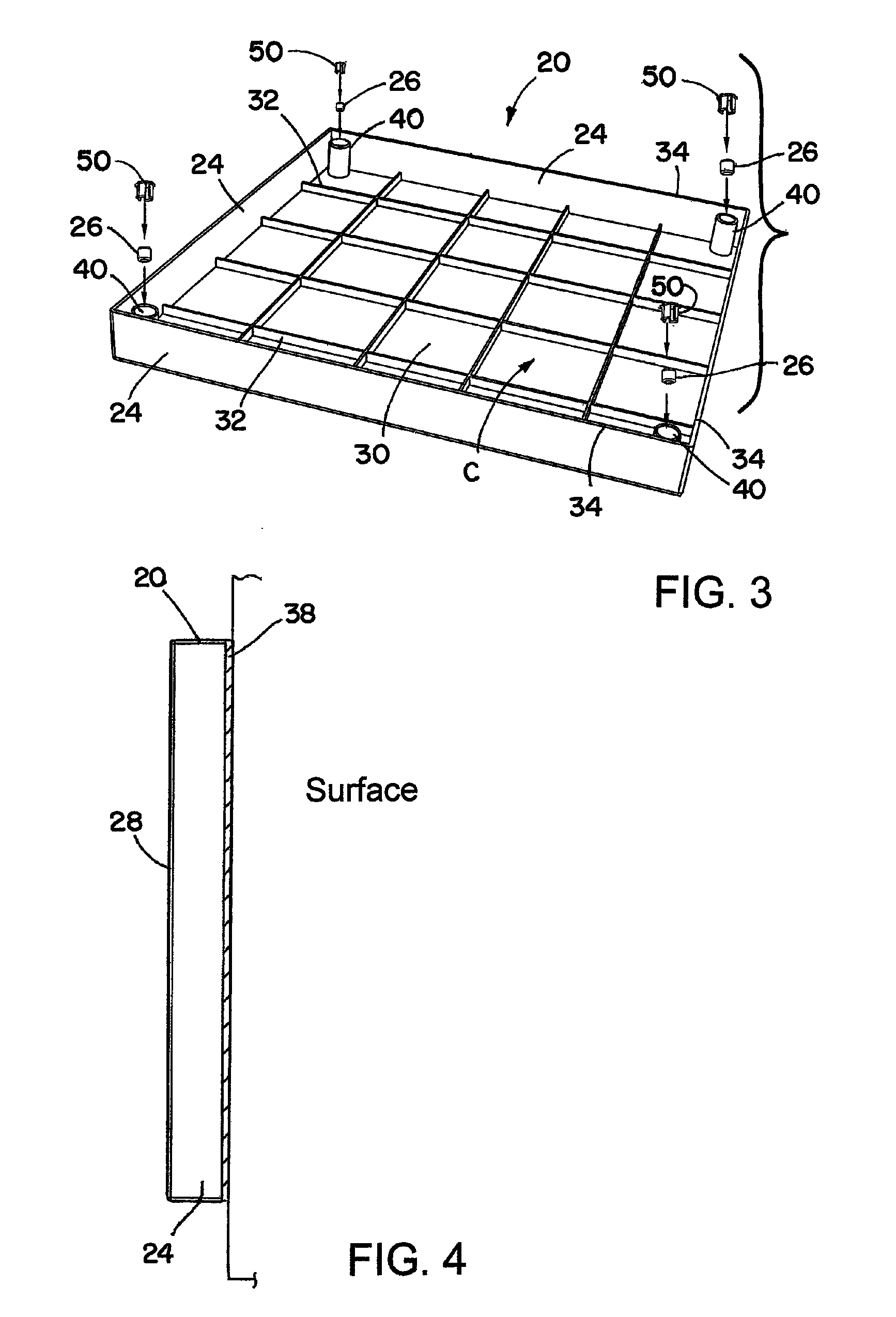
[0008]In one embodiment, the register cover attaches in seconds to the register through the use of magnets. The register cover is made from a plastic material, which may be molded from a plastic composite material, such as, PVC or ABS, for example. The register cover may take the form of a quadrilateral (e.g., square, rectangular, etc.) shape that has a top, bottom and four (4) sides (or side wall) that when put in place, covers the entire register. Alternatively, the register cover may take any desired shaped. When placed over the register, the sides of the register cover come in contact with the surface (e.g., wallboard, ceiling, or other finished or un-finished surface) that surrounds the register. The register cover forms a tight seal over the register, which eliminates the transfer of air from leaving and / or entering register. The register cover is attached to the register through one or more securing elements (e.g., magnets) that form a magnetic draw between the register cover and the register. In one embodiment, there are four (4) securing elements spaced apart in predetermined locations for securing the register cover to the register.
[0010]Another aspect of the invention relates to a method for attaching a magnetic register cover to a non-metallic register, the method including: providing a register cover, wherein the register cover includes a base member impervious to air, wherein the base member includes a front surface and a back surface; a side wall extending from the base member along a perimeter of the base member, wherein the side wall and the back surface form a cavity for receiving an associated non-metallic register and the cavity completely covers the associated non-metallic register; and a plurality of a magnets configured along the back surface to secure the base member to the associated non-metallic register; attaching one or more metallic mounts to the associated non-metallic register, wherein the one or more metallic mounts are configured to magnetically engage the magnets of the register cover; and placing the register cover over the associated non-metallic register, wherein the magnets of the register cover secure the register cover to the one or more metallic mounts and the register cover to create an interface between the sidewall and back surface of the register cover and the associated non-metallic register such that forced air is prevented from escaping through the interface.

Problems solved by technology

One problem with such conventional registers is that even when the louvers are in the closed position air can readily pass through the louvers.
Therefore, instead of bypassing the register, as intended by the user, the air escapes the louvers and warms or cools the area in which the register is located, thereby wasting energy.
Another problem with such conventional registers is that they are typically made from metal, which acts as a conductor and has very low insulative properties.
The transfer of air takes place through inadequate and / or inefficiently designed HVAC air registers / vents that are commonly installed in residential homes, as discussed above.

Method used


Image

  • Magnetic register cover
  • Magnetic register cover
  • Magnetic register cover

Examples


Embodiment Construction

[0023]The present invention will now be described with reference to the drawings, wherein like reference numerals are used to refer to like elements throughout.

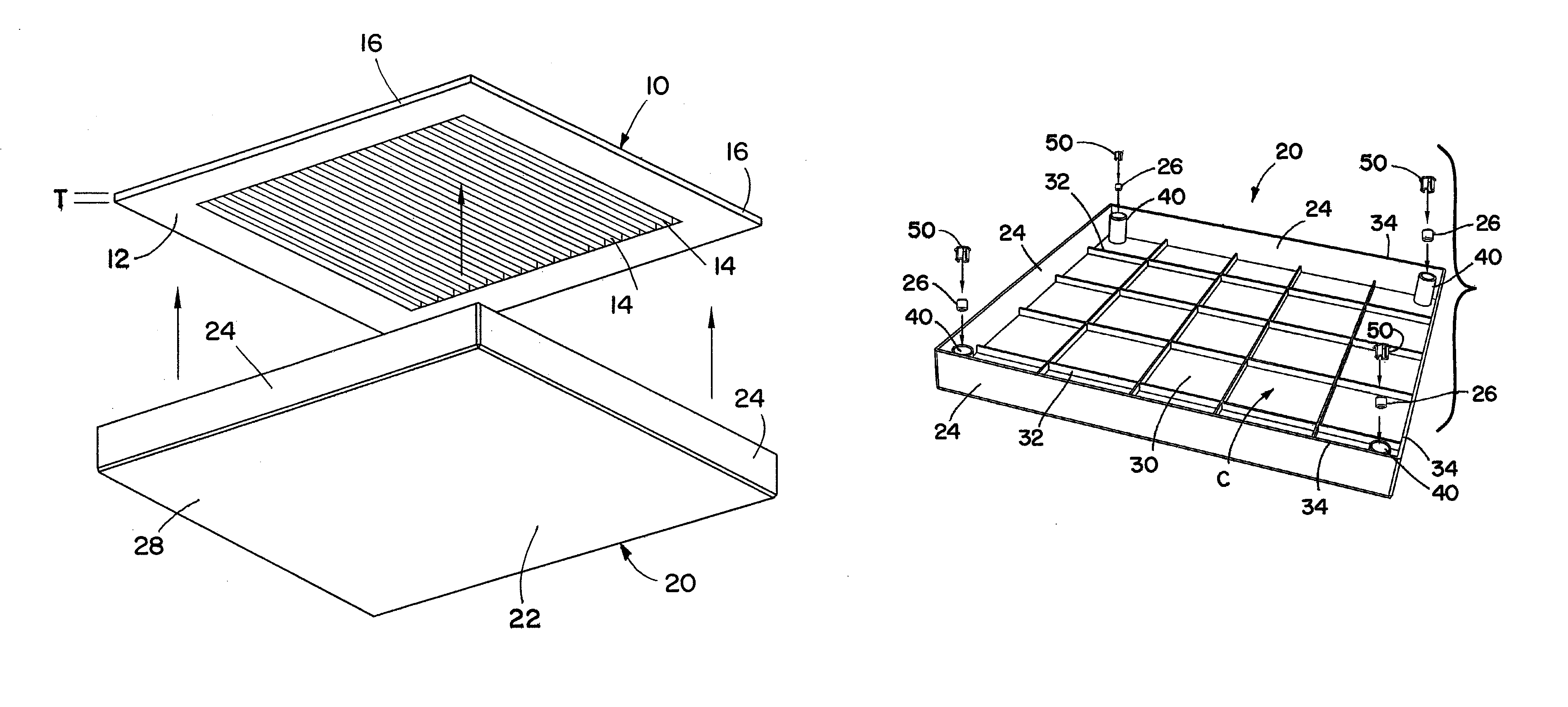
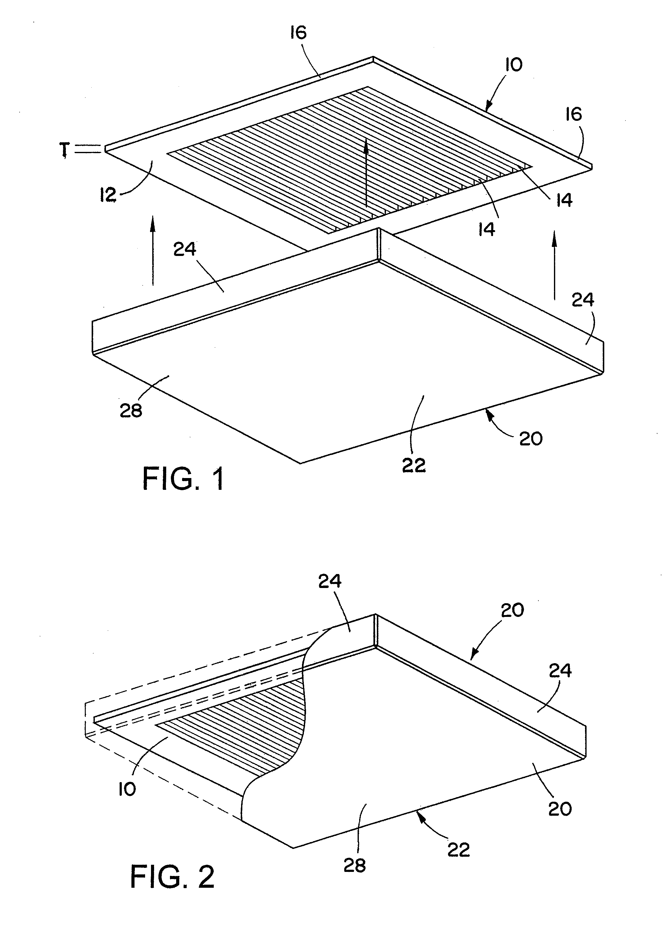
[0024]Referring to FIG. 1, a conventional register 10 for a heating, ventilation & air conditioning (HVAC) system is disclosed. The conventional register 10 illustrated in FIG. 1 is a ceiling register. In addition to ceiling registers, one of ordinary skill in the art will readily appreciate that the present invention may be used in connection with all types of registers (e.g., wall registers, louvered registers, patterned registers, etc.).

[0025]As shown in FIG. 1, the conventional register 10 includes face 12 having a plurality of openings 14 formed in the face 12 to allow forced air to escape through. The register 10 may further include louvers (not shown) that may be adjusted to control forced air flow through the register. The register 10 may also include sidewalls 16 that extend above a surface (e.g., wallboard, a wall, ...


PUM

PropertyMeasurementUnit
thicknessaaaaaaaaaa
thicknessaaaaaaaaaa
perimeteraaaaaaaaaa

Abstract

A register cover (also referred to as a vent cover) for use in a building that has heating, ventilation and air-conditioning (HVAC) systems that utilize air registers. The register cover completely covers the register and secures to the register using a magnet in order to substantially block the flow of forced air through the register that is covered by the register cover. In the case of a non-metallic register, a method is disclosed for retrofitting the non-metallic register by placing metallic mounts on the register in order to secure the register cover over the register with one or more magnets.

Description

RELATED APPLICATION DATA[0001]The present application claims the benefit of U.S. Provisional Application Ser. No. 61 / 206,050 filed on Jan. 26, 2009, the disclosure of which is herein incorporated by reference in its entirety.TECHNICAL FIELD OF THE INVENTION[0002]The present invention relates generally to the field of heating, ventilation and air-conditioning (HVAC) systems that utilize air registers (also referred to as vents or diffusers) that assist in the transfer of air from ducts into living and work areas within homes or buildings. In particular, the present invention relates to eliminating the transfer of air through inadequately and / or inefficiently designed air registers during times that the transfer of air through a register is undesirable.DESCRIPTION OF THE RELATED ART[0003]Air forced through heating, ventilation and air-conditioning (HVAC) systems is generally output through ducts to one or more registers (also referred to as a vents or diffusers), which are located in ...

Claims


Application Information

Patent Timeline
Patent Type & Authority Patents(United States)
IPC IPC(8): F24F13/08
CPCF24F13/20F24F13/082Y10T29/53
Inventor VIGGERS, CHERYL F.VIGGERS, ROBERT W.POIDOMANI, KAREN A.POIDOMANI, KEVIN
Owner ELIMA DRAFT
Learn More