
Method For Cutting Carbon Fiber Base

A carbon fiber base material and technology of base material, which is applied in the direction of chemical characteristics of fibers, cutting of textile materials, welding/welding/cutting articles, etc., can solve the problems of not being able to obtain the elastic modulus and strength of carbon short fibers.

Active Publication Date: 2012-12-05
TORAY IND INC
View PDF7 Cites 3 Cited by
  • Summary
  • Abstract
  • Description
  • Claims
  • Application Information

AI Technical Summary

Problems solved by technology

In addition, due to sintering at a high temperature of about 2000°C or higher, all the short carbon fibers themselves are carbonized, so the elastic modulus and strength of the short carbon fibers themselves cannot be obtained.

Method used


Image

  • Method For Cutting Carbon Fiber Base
  • Method For Cutting Carbon Fiber Base
  • Method For Cutting Carbon Fiber Base

Examples


Embodiment Construction

[0037] Hereinafter, preferred embodiments of the present invention will be described with reference to the drawings.

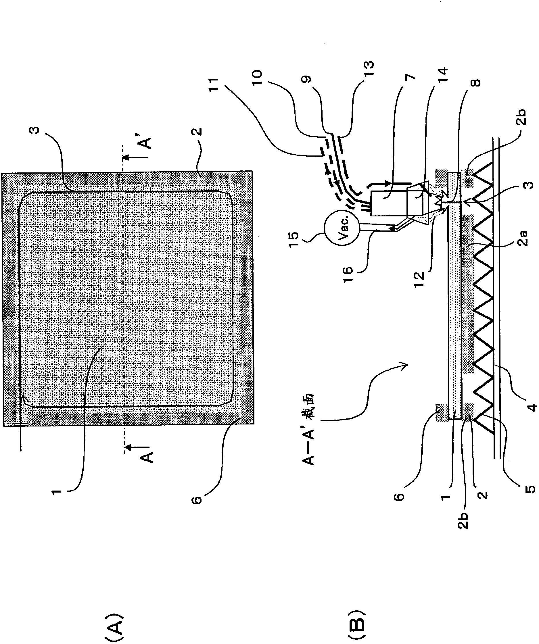
[0038] figure 1 The method of cutting a carbon fiber base material according to one embodiment of the present invention, in particular, shows an example of cutting the peripheral portion of a preform formed of a laminate of fabrics containing carbon fibers with a laser. Such as figure 1 As shown in (A), the preform 1 is placed on the support jig 2 , and laser cutting is performed along the cutting line (cutting position 3 ) along the periphery of the preform 1 . Such as figure 1 As shown in (B), in this embodiment, the support jig 2 is installed on the base 5 formed of a corrugated plate on the base 4, and the preform 1 is placed on the support jig 2 . The preform 1 is partly supported by support jigs 2, which are located on either side of the cutting position 2a, 2b. At the supporting position of the supporting jig 2b, the preform 1 is held from both side...


PUM


Abstract

Disclosed is a method for laser-cutting a carbon fiber base, e.g., a preform configured of sheets of fabric comprising carbon fibers, characterized by cutting the carbon fiber base under initial conditions which have been set so that the state of the base that is being cut with a laser can be inhibited or prevented from deviating from the desired state. With the method, it is possible to effectively eliminate various problems including dissipation of heat, positional shifting from the focal length range of the laser, and soot, and the carbon fiber base can be stably cut while being kept in the desired state.

Description

technical field [0001] The present invention relates to a method for cutting a carbon fiber base material at least composed of a fabric containing carbon fibers, and in particular to a method for cutting a suitable carbon fiber base material for the purpose of making The base material of fiber reinforced plastic (hereinafter, may be abbreviated as FRP [Fiber Reinforced Plastic] in some cases.) is cut into a predetermined shape with high precision. Background technique [0002] In recent years, chances of using fiber-reinforced plastics (hereinafter, sometimes abbreviated as CFRP [Carbon Fiber Reinforced Plastic (Carbon Fiber Reinforced Plastic)]) using carbon fibers are increasing for the purpose of reducing the weight of aircrafts and automobiles. For example, CFRP, which uses a carbon fiber fabric using carbon fiber bundles as a reinforcing fiber base material, is more advantageous than metal materials in terms of specific stiffness and specific strength, and is used in va...

Claims


Application Information

Patent Timeline
Patent Type & Authority Applications(China)
IPC IPC(8): D06H7/22B23K26/00B23K26/38
CPCB23K26/409B23K26/38B23K26/423B23K26/14B23K26/16B23K26/4085B23K2203/16B23K26/703B23K26/40B23K2103/172B23K2103/38B23K2103/50B23K2103/16D01F9/12D06H7/22
Inventor 山本晃之助山崎真明关户俊英
Owner TORAY IND INC
Learn More