Constant current control circuit controlling charging loop current

A constant current control circuit and charging circuit technology, which is applied to battery circuit devices, circuit devices, control/regulation systems, etc., can solve problems such as lower energy conversion efficiency, unreliable circuit operation, and large circuit heat generation, so as to eliminate eddy current loss Effects of heat, prevention of reverse voltage breakdown switch tube, volume reduction

Inactive Publication Date: 2014-07-02
SUZHOU SANSEN NEW ENERGY TECH
View PDF8 Cites 4 Cited by
  • Summary
  • Abstract
  • Description
  • Claims
  • Application Information

AI Technical Summary

Problems solved by technology

The traditional current control is mostly a linear circuit, and the disadvantage is that it is bulky; of course, there are also a few that use the PWM method, but because there is no feedback winding in the circuit, the energy is wasted in the MOS circuit, resulting in a waste of energy and greatly reducing the energy consumption. The conversion efficiency; at the same time, it also makes the whole circuit heat relatively large, and the circuit work is unreliable

Method used


Image

  • Constant current control circuit controlling charging loop current
  • Constant current control circuit controlling charging loop current

Examples


Embodiment Construction

[0013] Specific embodiments of the present invention will be described in detail below in conjunction with the accompanying drawings.

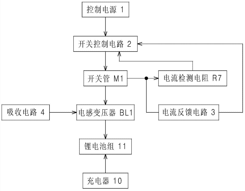
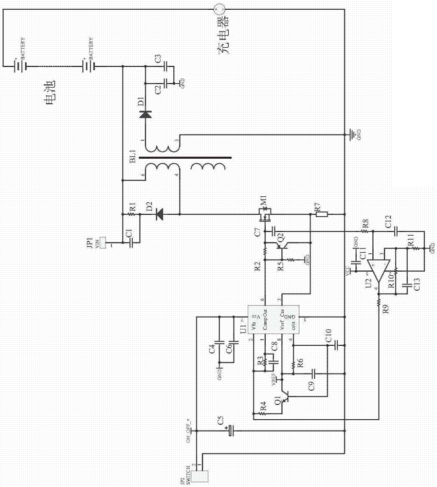
[0014] Such as figure 1 , figure 2 As shown, the constant current control circuit for controlling the charging circuit current according to the present invention includes a current feedback circuit 3, a snubber circuit 4 connected in series by a snubber resistor R1 and a snubber diode D2, a switch tube M1, and a PWM-based control chip U1 (UC3842) The switch control circuit 2 that controls the switching of the switch tube M1 and the inductance transformer BL1. One end of the primary coil of the inductance transformer BL1 is connected to the output terminal (drain) of the switch tube M1, and the other end of the primary coil of the inductance transformer BL1 is used as The access terminal JP1 connected to the charging circuit for charging the lithium battery pack 11 by the charger 10, the absorbing circuit 4 is connected in parallel to the two...


PUM


Abstract

The invention discloses a constant current control circuit controlling a charging loop current. The constant current control circuit is small in size and can reduce energy consumption. The constant current control circuit comprises a switch tube, a switch control circuit and an induction transformer, wherein the switch control circuit is used for controlling switching on and switching off of the switch tube, one end of a primary side coil of the induction transformer is connected with the output end of the switch tube, and the other end of the primary side coil serves as the switching-in end connected with a charging loop; one end of a secondary side coil of the induction transformer is grounded, the other end of the secondary side coil is connected with the switching-in end of the primary side coil through a reverse-preventing diode, the switch control circuit is based on a PWM control chip, a current detection resistor is arranged between the grounded end and the power end of the switch tube, and the grounded end of the switch tube is connected to the feed-in end of the switch control circuit through a current feedback circuit. The constant current control circuit is mainly used in the charging loop when a lithium battery is charged by a charger.

Description

technical field [0001] The invention relates to a constant current control method, in particular to a constant current control circuit used for controlling the current of a charging circuit during the charging process of a battery by a charger. Background technique [0002] With the rapid development of science and technology and the continuous popularization of new energy sources, it has become a common technical requirement to control the current by technical means, especially in the active intervention management of lithium-ion battery charging and the limitation of discharge current. The traditional current control is mostly a linear circuit, and the disadvantage is that it is bulky; of course, there are also a few that use the PWM method, but because there is no feedback winding in the circuit, the energy is wasted in the MOS circuit, resulting in a waste of energy and greatly reducing the energy consumption. The conversion efficiency; at the same time, it also makes th...

Claims


Application Information

Patent Timeline
Patent Type & Authority Applications(China)
IPC IPC(8): H02J7/00H02M3/335
Inventor 陆焱蒋闯张潮海张玮
Owner SUZHOU SANSEN NEW ENERGY TECH
Why Eureka
Try Eureka