
Full-sealing device for upper portion of aluminum electrolytic cell with prebaked anode

A technology of aluminum electrolytic cell and prebaked anode, which is applied in the field of aluminum electrolysis, and can solve the problems that the prebaked anode aluminum electrolytic cell cannot be completely sealed, damages the anode guide rod and anode busbar, and sparks between the anode guide rod and the anode busbar , to achieve the effect of eliminating the large busbar frame of the anode, reducing heat loss and realizing clean production

Active Publication Date: 2017-08-29
CHONGQING UNIVERSITY OF SCIENCE AND TECHNOLOGY
View PDF9 Cites 3 Cited by
  • Summary
  • Abstract
  • Description
  • Claims
  • Application Information

AI Technical Summary

Problems solved by technology

The disadvantages of this sealing structure are: a) the tank covers that are close to each other are deformed by heat, and the edges of the tank covers cannot be moved closer together, resulting in the leakage of electrolytic fume; b) a large amount of electrolytic fume is also leaked from the gap of the U-shaped slot through which the anode guide rod passes
When it is lifted to the upper limit, clamp the anode guide rod and remove the lifting busbar frame. In this process, the anode guide rod and the anode busbar are likely to catch fire, which will damage the anode guide rod and the anode busbar, which has a very large Therefore, it must be operated openly under the close supervision of the operator. This is the root cause of the prebaked anode aluminum electrolytic cell not being fully sealed.

Method used


Image

  • Full-sealing device for upper portion of aluminum electrolytic cell with prebaked anode

Examples


Embodiment Construction

[0026] Embodiments of the present invention will be described in further detail below in conjunction with the accompanying drawings.

[0027] In this embodiment, the orientation or positional relationship indicated by the terms "upper", "lower", "left", "right", "front", "rear", "upper end" and "lower end" are based on the orientation or positional relationship shown in the drawings, It is for the convenience of description only, and does not indicate or imply that the device or element referred to must have a specific orientation, be constructed in a specific orientation, or operate, and thus should not be construed as limiting the present invention.

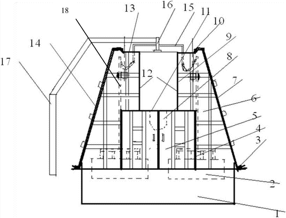
[0028] Such as figure 1 The upper full sealing device of the prebaked anode aluminum electrolytic cell includes an anode guide rod 18, an anode bus bar 16, and a column bus bar 17 connected to the anode bus bar 16. The anode system 2 is installed at the lower end of the anode guide bar 18. The anode large busbar 16 is one, fix...


PUM


Abstract

The invention provides a full-sealing device for the upper portion of an aluminum electrolytic cell with a prebaked anode. The full-sealing device comprises an anode guide rod, an anode large busbar and a stand column busbar connected with the anode large busbar. The anode large busbar is fixedly arranged in the center of the top of the electrolytic cell. Aluminum small busbars are further symmetrically arranged at the left end and the right end of the anode large busbar and connected with the upper end of the anode guide rod to supply current to an anode system of the electrolytic cell. A sealing cover is further arranged above the electrolytic cell, comprises an end face cover plate and a side face outer cover body and further comprises a top smoke blocking plate, side sealing plates and a bottom smoke blocking plate which are mounted on a bearing truss on the upper portion of the electrolytic cell. The opening end of the upper portion of the electrolytic cell is fully sealed through the sealing cover. According to the full-sealing device, the structure of a traditional anode large busbar is improved, the full-sealing device is provided on the basis of the structure of the improved anode large busbar and fully seals the upper portion of the electrolytic cell, electrolytic smoke leakage and disorganized emission are eradicated, and clean production is achieved.

Description

technical field [0001] The invention relates to the technical field of aluminum electrolysis, in particular to a full sealing device for the upper part of a prebaked anode aluminum electrolytic cell. Background technique [0002] A large amount of harmful fume and dust containing HF gas will be produced in the process of aluminum electrolysis. In order to prevent the random discharge of harmful fume, the anode system of the electrolytic cell is usually sealed, and the flue gas is drawn into the purification system through the smoke exhaust channel for centralized treatment. . [0003] Therefore, the sealing device is a very important part of the aluminum electrolytic cell. Most of the existing prebaked anode aluminum electrolytic cell sealing devices are made of aluminum alloy small cell covers, the lower part rests on the edge of the electrolytic cell, and the upper part is buckled on the smoke shield On the top, the anode guide rod passes through the U-shaped groove on th...

Claims


Application Information

Patent Timeline
Patent Type & Authority Applications(China)
IPC IPC(8): C25C3/16C25C3/08C25C3/22
CPCC25C3/08C25C3/16C25C3/22
Inventor 田应甫尹建国李贺松周雪娇
Owner CHONGQING UNIVERSITY OF SCIENCE AND TECHNOLOGY
Learn More