On-line/at-line monitoring of residual chemical by surface enhanced Raman spectroscopy

a raman spectroscopy and surface enhancement technology, applied in the direction of optical radiation measurement, instruments, spectrometry/spectrophotometry/monochromators, etc., can solve the problems of inability to reliably and cost-effectively measure chemical concentrations below one percent, small effective amounts are very slightly more than inadequate and ineffective amounts, and achieve enhanced surface effects

Inactive Publication Date: 2012-10-23
CONOCOPHILLIPS CO
View PDF5 Cites 35 Cited by
  • Summary
  • Abstract
  • Description
  • Claims
  • Application Information

AI Technical Summary

Problems solved by technology

However, small effective amounts are very slightly more than amounts that are inadequate and ineffective.
These protective chemicals are typically consumed at non-linear and unpredictable rates so trying to maintain a minimum, but yet effective amount is very difficult.
There are two fundamental challenges for efficient use of these types of chemicals.
First, equipment that is reliable and cost effective for measuring chemical concentrations below one percent are generally unavailable or impractical.
Secondly, since the chemical concentration may fall below the threshold for effective amounts without warning, it is common for pipeline operators and owners of vessels and storage tanks to simply use quite a bit more than necessary as a precaution against not having enough.
Since the chemicals are very expensive, any over-use of the chemicals can directly and substantially impact the bottom line of the end-user.

Method used


Image

  • On-line/at-line monitoring of residual chemical by surface enhanced Raman spectroscopy
  • On-line/at-line monitoring of residual chemical by surface enhanced Raman spectroscopy
  • On-line/at-line monitoring of residual chemical by surface enhanced Raman spectroscopy

Examples


Embodiment Construction

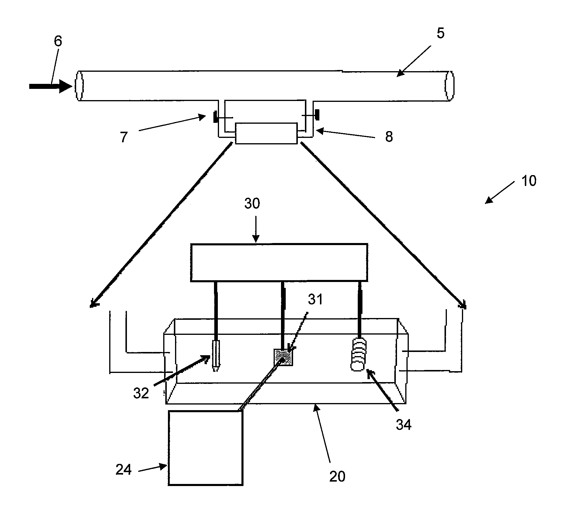
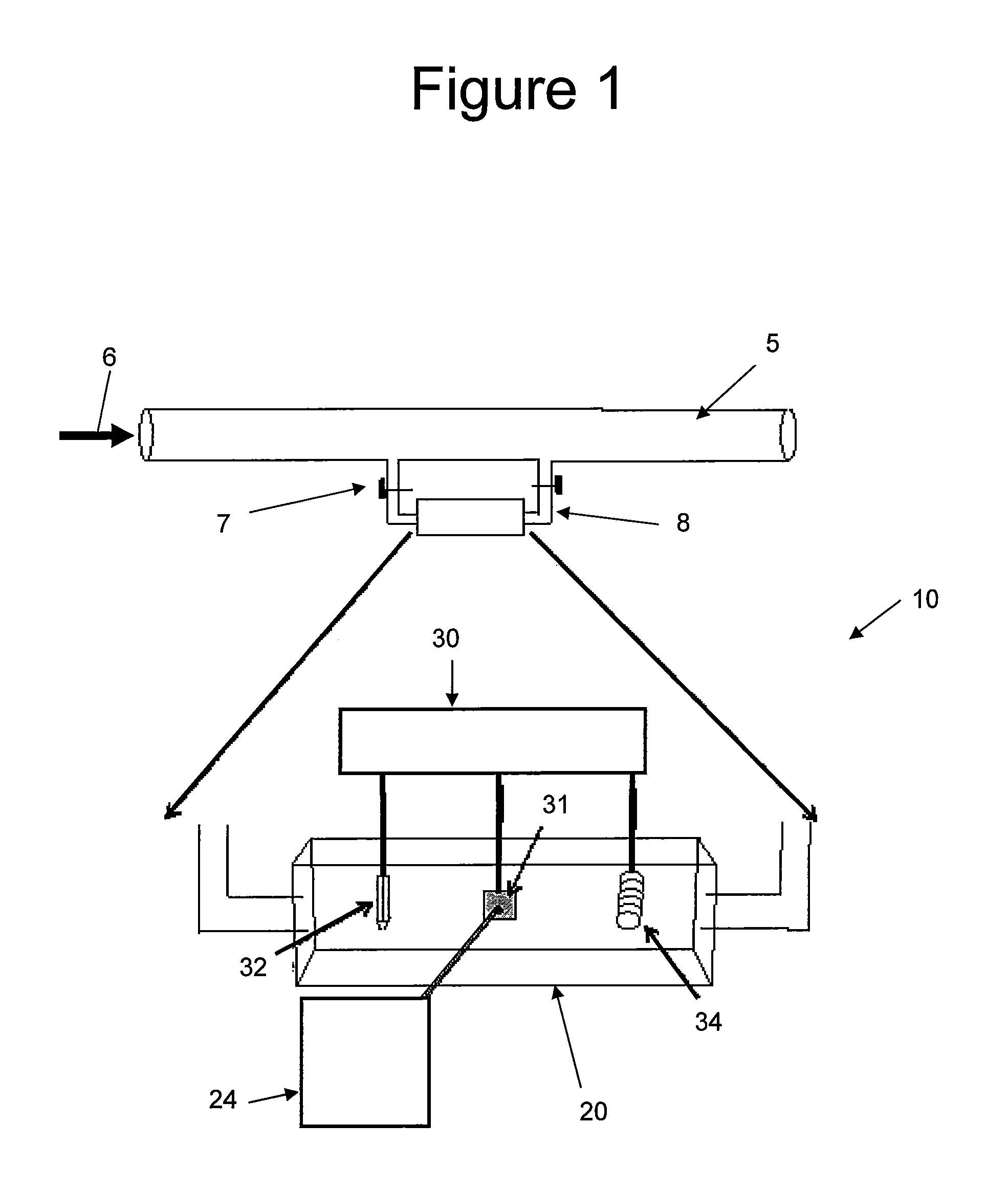
[0010]Turning now to the preferred arrangement for the present invention, reference is made to the drawings to enable a more clear understanding of the invention. However, it is to be understood that the inventive features and concept may be manifested in other arrangements and that the scope of the invention is not limited to the embodiments described or illustrated. The scope of the invention is intended only to be limited by the scope of the claims that follow.

[0011]The following detailed description of embodiments of the present invention references the accompanying drawings that illustrate specific embodiments in which the invention may be practiced. The embodiments are intended to describe aspects of the technology in sufficient detail to enable those skilled in the art to practice the invention. Other embodiments can be utilized and changes can be made without departing from the scope of the present invention. The following detailed description is, therefore, not to be taken ...


PUM


Abstract

Target chemicals are monitored at very low concentrations in pipelines or vessels such as storage tanks using surface enhanced Raman spectroscopy analysis of a sample. A liquid sample having a target chemical such as biocides, corrosion inhibitors, scale inhibitors, anti-foaming agents, emulsion breakers, and hydrate inhibitors are tested while exposed to a prepared and charged surface of a coupon so as to draw the target material to the prepared and charged surface. The charged surface is fairly precisely charged using two other electrodes to calibrate the charge on the surface of the coupon. With the target substance presumably drawn to the coupon, the molecules on the surface of the coupon are excited by monochromatic light such as from a laser to induce vibrations within the molecules. The vibrations of the molecules reflect and scatter the monochromatic light in distinctive manners such that the collected light from the surface provides an indication of the presence of the target substance in the sample and a quantitative indication of the concentration of the target material in the sample. With the ability at lower power and reasonable cost to sense the presence well down below one percent and into the ppm range provides the opportunity to more precisely and efficiently add such chemicals to operating pipelines and storage tanks.

Description

CROSS-REFERENCE TO RELATED APPLICATIONS[0001]This application is a continuation-in-part application which claims benefit under 35 USC §120 to U.S. application Ser. No. 12 / 047,141 filed Mar. 12, 2008, entitled “METHOD AND APPARATUS FOR SURFACE ENHANCED RAMAN SPECTROSCOPY,” and a continuation-in-part application which claims the benefit under 35 USC §120 to U.S. application Ser. No. 12 / 116,415 filed May 7, 2008, entitled “METHOD AND APPARATUS FOR SURFACE ENHANCED RAMAN SPECTROSCOPY,” issued Aug. 24, 2010 as U.S. Pat. No. 7,782,448, both of which are incorporated herein in their entirety. A related patent application is filed on the same date as this patent application entitled “Residual Chemical Monitoring System Using Surface Enhanced Raman Spectroscopy”.STATEMENT REGARDING FEDERALLY SPONSORED RESEARCH OR DEVELOPMENT[0002]None.FIELD OF THE INVENTION[0003]This invention relates to monitoring the presence of chemicals in solutions in pipelines and to periodically testing the materials ...

Claims


Application Information

Patent Timeline
Patent Type & Authority Patents(United States)
IPC IPC(8): G01J3/44G01J3/443G01J3/30
CPCG01N21/03G01N21/658G01N2021/651
Inventor SARDASHTI, MAZIARBLUMER, DAVID J.MCENROE, FRANK J.
Owner CONOCOPHILLIPS CO
Why Eureka
Try Eureka