Deposition box for silicon-based thin film solar cell
a solar cell and silicon-based technology, applied in the field of solar cell technology, can solve the problems of low plasma concentration, long deposition period, low deposition rate,
- Summary
- Abstract
- Description
- Claims
- Application Information
AI Technical Summary
Benefits of technology
Problems solved by technology
Method used
Image
Examples
embodiment 1
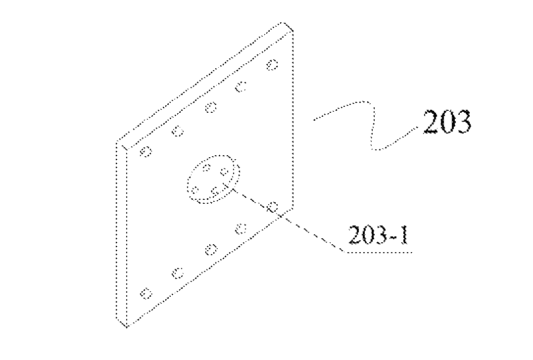
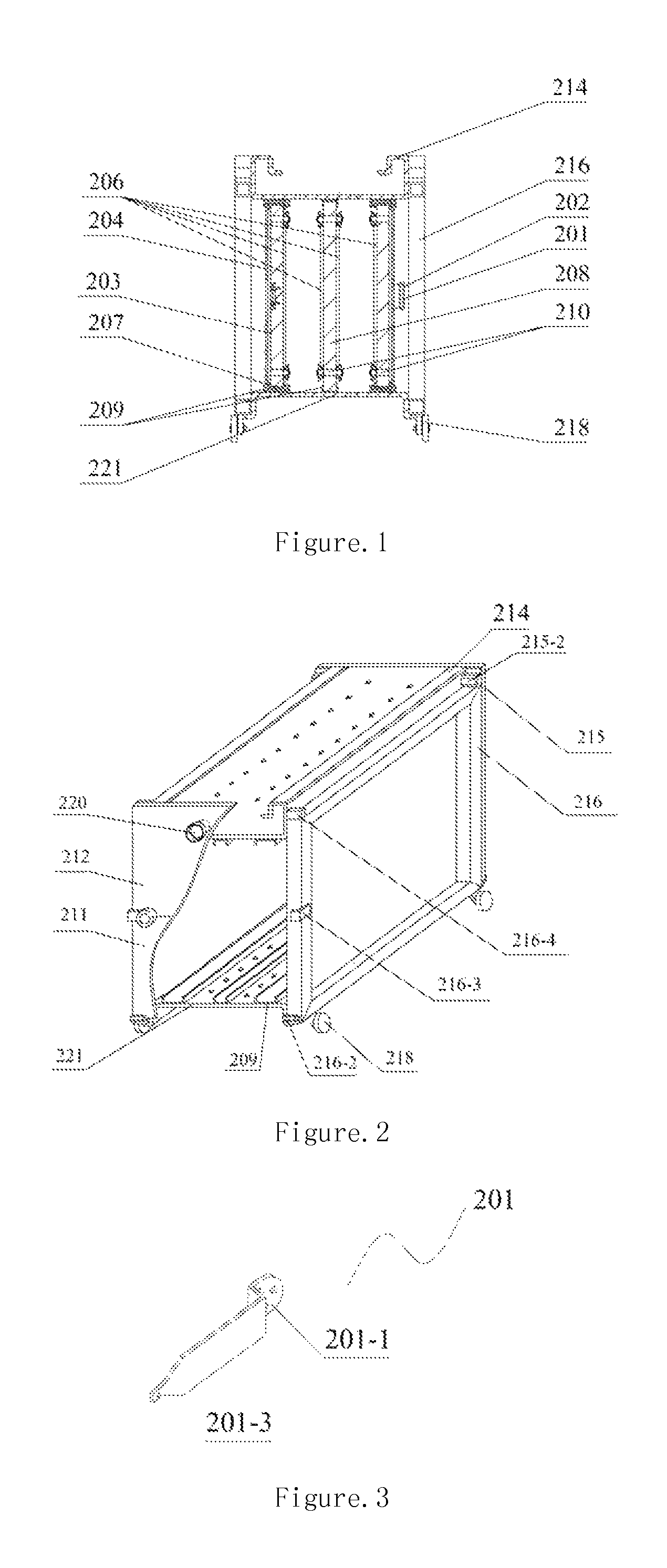
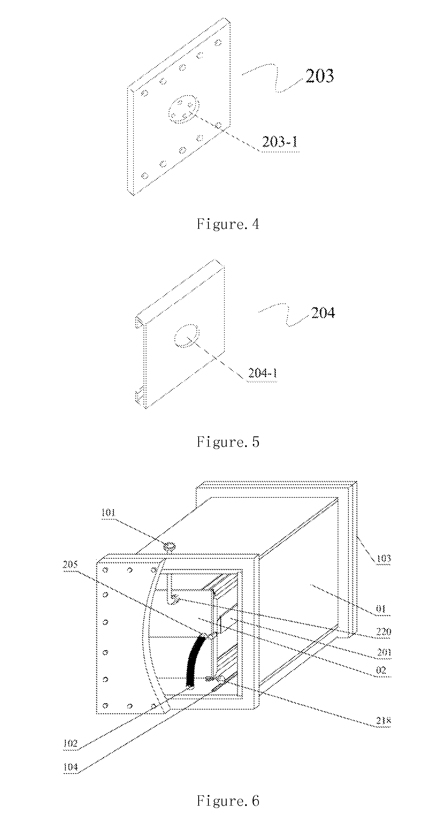
[0031]Electrode plates are vertically placed. Cathode plates have circular feed-in ports, and feed-in components have flat waists and semi-circular feed-in interfaces.
[0032]The principle of this embodiment is illustrated with FIGS. 1-6. In deposition box 02, two cathode plates 203 surround one anode plate 208. PECVD deposition system consists of vapor deposition chamber, gas system, electrical power system, vacuum system, heating system, control system, and so on. Gas system mainly provides different gases and gas lines for vapor deposition. Electrical power system mainly provides high-frequency or very-high-frequency electrical power source to discharge plasma for film deposition. Vacuum system mainly provides vacuum pumping machines and vacuum pipelines. Heating system mainly supplies heat for vapor deposition chamber. Control system mainly controls the parameters of deposition process. Vapor deposition chamber is the apparatus for realizing thin film deposition with gases on subs...
embodiment 2
[0035]Electrode plates are vertically placed. Cathode plates have circular feed-in ports. Feed-in components have flat waists and semi-circular feed-in interface. Cathode plates are insulated from shields and through holes are set in the shields of cathode plates.
[0036]Deposition box in FIG. 7 is the same as that in Embodiment 1, in which 8 glass substrates 206 can be processed at the same time. Two cathode plates 203 surround one anode plate 208, and four pairs of electrodes can be formed by two anode plates 208 and four cathode plates 203. In such a configuration, eight substrates can be coated with thin films at the same time. Detailed processes are illustrated as follows:
[0037]a) Place 8 glass substrates (1640 mm×707 mm×3 mm) with 600-nm transparent conducting thin films in the substrate position in deposition box 02. Film side of the substrate faces outside, while glass side of the substrate faces toward electrode plate.
[0038]b) Open the active door 103 of the vacuum chamber, a...
embodiment 3
[0045]Electrode plates are vertically placed. Cathode plates have circular feed-in ports. Feed-in components have flat waists and semi-circular feed-in interface. Cathode plates are insulated from shields and through holes are set in the shields of cathode plates.
[0046]Deposition box in FIG. 8 is the same as that in Embodiment 1, in which 24 glass substrates 206 can be processed at the same time. Two cathode plates 203 surround one anode plate 208, and twelve pairs of electrodes can be formed by six anode plates 208 and twelve cathode plates 203. In such a configuration, twenty four substrates can be coated with thin films at the same time. Detailed processes are illustrated as follows:
[0047]a) Place 24 glass substrates 206 (1640 mm×707 mm×3 mm) with 600-nm transparent conducting films in the substrate position in deposition box 02. Film side of the substrate faces outside, while glass side of the substrate faces toward electrode plate.
[0048]b) Open the active door 103 of the vacuum...
PUM
| Property | Measurement | Unit |
|---|---|---|
| frequency | aaaaa | aaaaa |
| frequency | aaaaa | aaaaa |
| excitation frequency | aaaaa | aaaaa |
Abstract
Description
Claims
Application Information
 - R&D
- Intellectual Property
- Life Sciences
- Materials
- Tech Scout
- Unparalleled Data Quality
- Higher Quality Content
- 60% Fewer Hallucinations
Browse by: Latest US Patents, China's latest patents, Technical Efficacy Thesaurus, Application Domain, Technology Topic, Popular Technical Reports.
© 2025 PatSnap. All rights reserved.Legal|Privacy policy|Modern Slavery Act Transparency Statement|Sitemap|About US| Contact US: help@patsnap.com


