Valve, namely for bottles for ultra-high purity gas

a valve and ultra-high purity technology, applied in the field of valves, can solve the problems of reducing the production yield, reducing the service life of the valve, etc., and achieve the effect of good gas tightness of the obturating member

Active Publication Date: 2012-10-30
ROTAREX SA
View PDF22 Cites 17 Cited by
  • Summary
  • Abstract
  • Description
  • Claims
  • Application Information

AI Technical Summary

Benefits of technology

[0012]Moreover, the annular bead provided on the radial lip of the holding ring permits the annular seal to be over compressed into the annular groove, thereby filling up the total space and obviating dead spots that could trap the gas. It should be noted here that the dimensions of the annular seal and the cavity are preferably chosen such that the compression forces are initially generated by the annular bead. Therefore, when the holding ring is mounted, the seal will be compressed by the annular bead. Another advantage of the annular bead is that it punctually creates an important compression zone with the annular seal and forms a gas-tight / sealing barrier.
[0013]Finally, the fixation by welding on the totality of the circumference and in a gas-tight manner constitutes a guarantee of gas-tightness at the back of the annular seal which cannot be affected by crimping or screwing. For practical reasons and on the grounds of precision and thermal control, lasers are particularly preferred for the welding operation. The weld can be made with or without the supply of material. Other welding techniques that allow the realisation of precise welds can also be employed, such as by electron beams. It should also be noted that fixing the holding ring by welding provides a simple assembly of the ring onto the body of the obturating member essentially without imposing any stress on the annular seal—apart from the stresses generated by the annular bead—consequently avoiding any damage during assembly.
[0014]According to one embodiment, the free end of the obturating member includes a radial projection of the end which penetrates radially into an internal annular shoulder of the annular seal. The free end of the obturating member can be truncated in shape that reduces in size from the shoulder towards the radial projection. This radial projection of the end has two purposes: (1) when the annular seal is assembled, it holds it in place; (2) once the holding ring is welded, it produces a gas-tight barrier effect similar to that obtained with the annular bead on the lip of the holding ring. In this variant, the annular seal is therefore confined in the annular groove that comprises at its entrance two gas-tight barriers to prevent any gas passing towards the back of the annular seal.
[0015]Preferably, the circumferential external weld between the holding ring and the obturating member is realised axially and set back with respect to the shoulder. To that end, the obturating member can comprise a peripheral annular shoulder, on which the annular seal leans, but axially set back with respect to this, the holding ring being then welded to the obturating member at this peripheral annular shoulder. This axial offset enables welding to be carried out at a certain distance from the seal thereby ensuring that the heat does not damage it.
[0021]Consequently, the valve according to the invention proves to be particularly advantageous for ultra-high purity applications, in particular because of the good gas-tightness of its obturating member without dead volumes. For use as a valve of a gas bottle, the valve body is designed to be fixed onto a bottle and the opening of the entrance of the flow channel typically opens into the interior of the bottle. However, the present valve can also be used as a release valve / tap in a system for (fluid) gas distribution. In this case, the valve body is preferably modified such that the inlet and outlet openings can be connected to the pipes or other elements of the gas distribution system.

Problems solved by technology

For the semiconductor industry, for example, distribution systems for high quality gas have been developed because the presence of impurities in the gas could irreparably affect the electrical properties of the components and consequently also diminish the production yields.
Moreover, these gases are expensive, highly reactive, corrosive and / or toxic, and it is therefore essential to have reliable and suitable equipment.
In spite of these efforts, the design of certain valves that are conventionally used in applications requiring high purity is not considered to be completely satisfactory.
However, in the designs mentioned above, the presence of teeth implies an abrasion of the seal, which would generate particles, and bring about dead spots (volumes not occupied by the seal).
For a screwed ring, gas-tightness cannot be guaranteed at the threads, and any rubbing on the latter could also generate particles.
Furthermore, when screwing the ring, this can exert torsional forces on the seal, which can deform it.
Finally, on assembling by crimping, it is neither possible to guarantee a gas-tight assembly nor to precisely control the tenure of the annular seal.
Consequently, the present designs comprise dead zones and potential leakage zones, which are not wanted for applications involving pure and ultra-pure gases.

Method used


Image

  • Valve, namely for bottles for ultra-high purity gas
  • Valve, namely for bottles for ultra-high purity gas
  • Valve, namely for bottles for ultra-high purity gas

Examples


Embodiment Construction

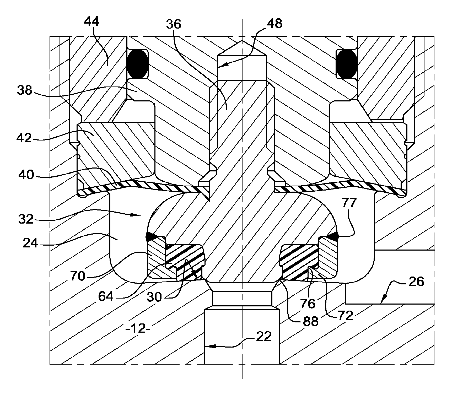
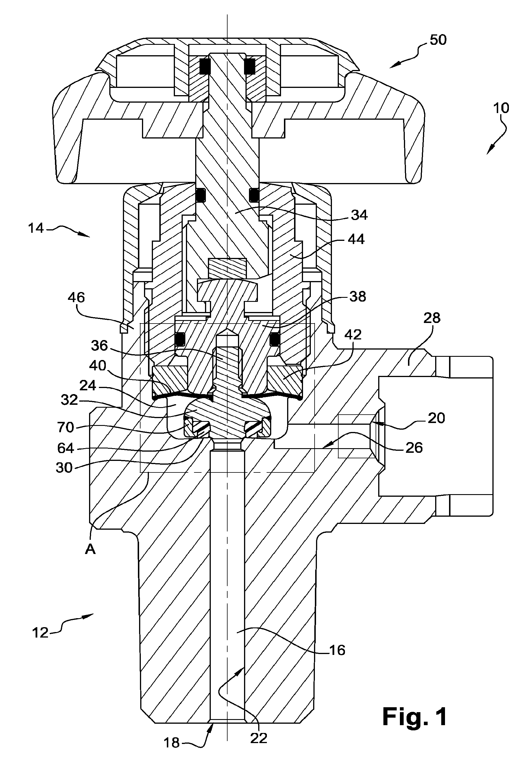
[0028]FIG. 1 represents a longitudinal cross section of a preferred variant of the present valve 10, which comprises a valve body and a manual control piece each designated respectively 12 and 14. The valve body 12 is designed to be screwed on a gas bottle (not shown) and comprises a gas flow channel 16 extending between a gas inlet 18 and a gas outlet 20.

[0029]In the present execution, the flow channel 16 is formed by an entrance channel 22 connecting the entry inlet 18 to the chamber of the valve 24 and an outlet channel 26 connecting the valve chamber to the exit outlet 20. The entry channel 22 passes through the lower part of the body 12 that is provided with a thread (not shown) that enables the valve to be screwed onto the bottle. The exit channel 26 leads to a part that forms connection 28.

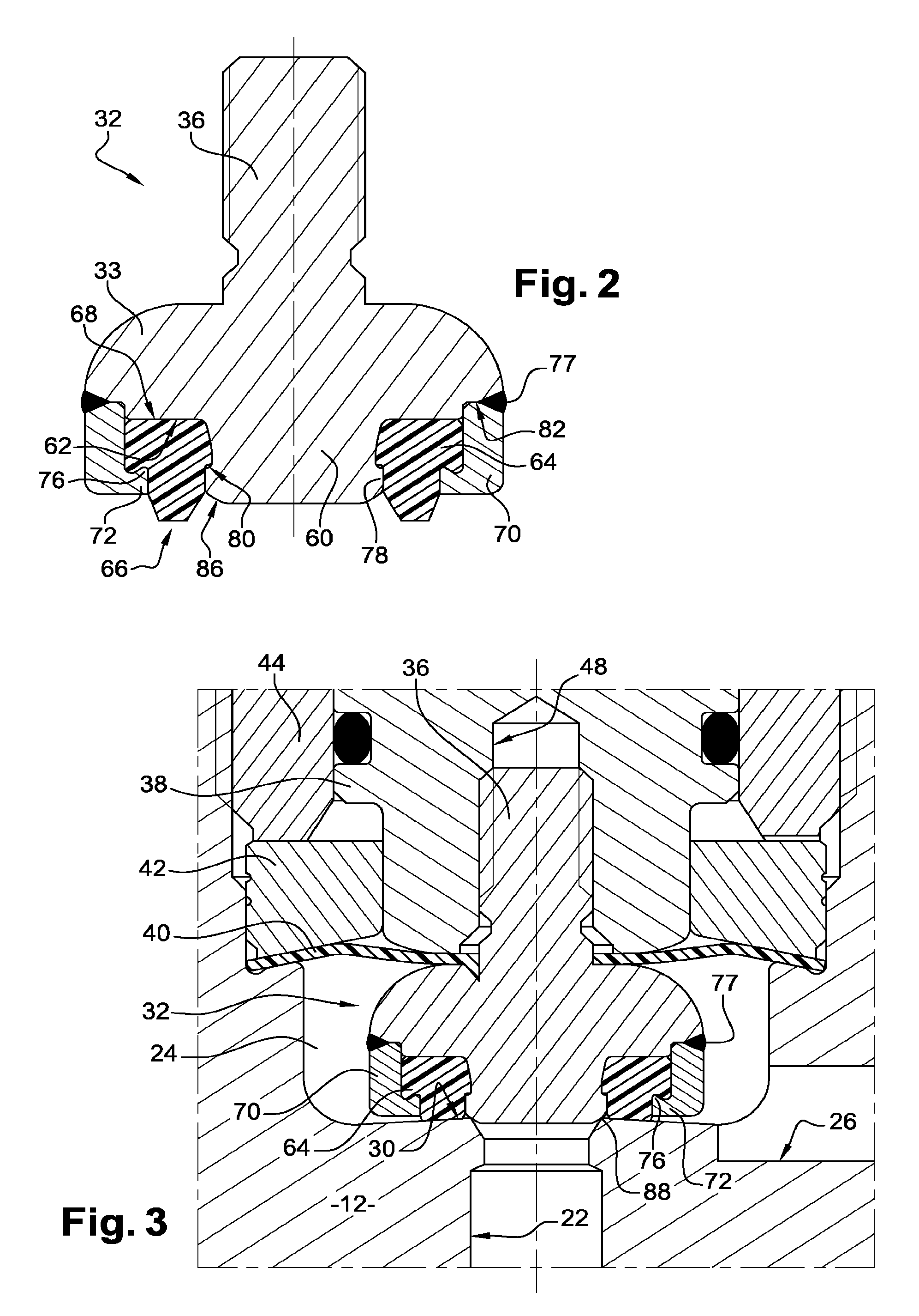
[0030]The end of the entry channel 22 arriving in the chamber 24 is surrounded by a first sealing seat 30 comprising an annular gas-tight seal, with which cooperates an obturating member 32...


PUM


Abstract

A valve for pressurized or liquefied gas comprises a valve body (12) with a gas flow channel (16) and in this channel a sealing seat (30) for an open / close element (32) having a free end (60) where a shoulder (62) is provided. An annular seal (64) is mounted on the free end (60) of the open / close element (32), the annular seal (64) having a front end face (66) facing the sealing seat (30) and a rear end face (68) resting on the shoulder (62) of the open / close body. A holding ring (70) surrounds the annular seal (64) circumferentially and comprises a radial lip (72) that bears on the outer edge of the front end face (66) of said annular seal (64). The annular seal (64) includes an outer annular shoulder (74) on the edge of its front end face and the radial lip (72) with the holding ring (70) has an annular bead (76) facing this outer annular shoulder (74) of the annular seal (64). The holding ring (70) is fixed to the open / close element (32) by a leaktight outer circumferential weld (77), so that the annular bead (76) passes axially into the outer annular shoulder (74) of the annular seal (64) to compress it.

Description

TECHNICAL FIELD OF THE INVENTION[0001]The present invention concerns a valve, namely for bottles (or cylinders) of gas or liquefied gas. This valve is particularly well adapted for applications involving ultra-pure gases.BRIEF DESCRIPTION OF RELATED ART[0002]The increasingly widespread use of special gases and the high level of purity required today by certain industries has resulted in continual efforts by manufacturers of valve systems, valves and other equipment for gas distribution to improve the quality and the integrity of their products.[0003]For the semiconductor industry, for example, distribution systems for high quality gas have been developed because the presence of impurities in the gas could irreparably affect the electrical properties of the components and consequently also diminish the production yields. Moreover, these gases are expensive, highly reactive, corrosive and / or toxic, and it is therefore essential to have reliable and suitable equipment.[0004]In spite of...

Claims


Application Information

Patent Timeline
Patent Type & Authority Patents(United States)
IPC IPC(8): F16K1/02
CPCF16K1/02F16K1/46F16K1/302F16K1/36F17C13/04
Inventor MUZZO, PAULKREMER, PAULGRZYMLAS, WALTER
Owner ROTAREX SA
Why Eureka
Try Eureka