
Manufacturing method of flexible display panel and manufacturing method of electro-optical apparatus

a manufacturing method and display panel technology, applied in the field of flexible display panel and fabricating method thereof, can solve the problem of thin glass substrates liable to crack, and achieve the effect of light and slim appearan

Active Publication Date: 2012-10-30
AU OPTRONICS CORP
View PDF16 Cites 28 Cited by
  • Summary
  • Abstract
  • Description
  • Claims
  • Application Information

AI Technical Summary

Benefits of technology

[0008]The present invention is directed to a flexible display panel, in which a conventional glass substrate is substituted by a flexible substrate, so that a display applying the flexible display panel is bendable, and may have a light and slim appearance.
[0016]In the present invention, since the flexible substrates are applied to serve as the substrates of the flexible display panel, compared to the conventional display panel applying rigid glass substrates, the flexible display panel of the present invention can be bended to tolerate a specific degree of deformation, and a display applying such display panel may have a light and slim appearance. Moreover, the present invention also provides the aforementioned method for fabricating the flexible display panel, and the electro-optical device applying the flexible display panel can also be bended, and has the light and slim appearance.

Problems solved by technology

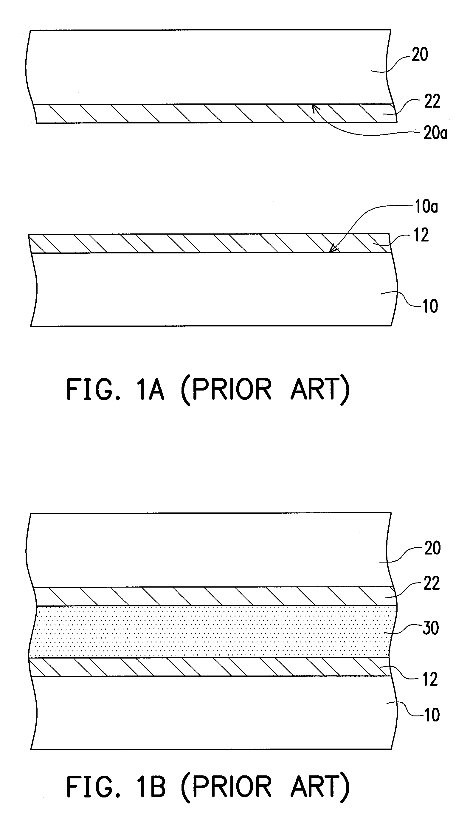
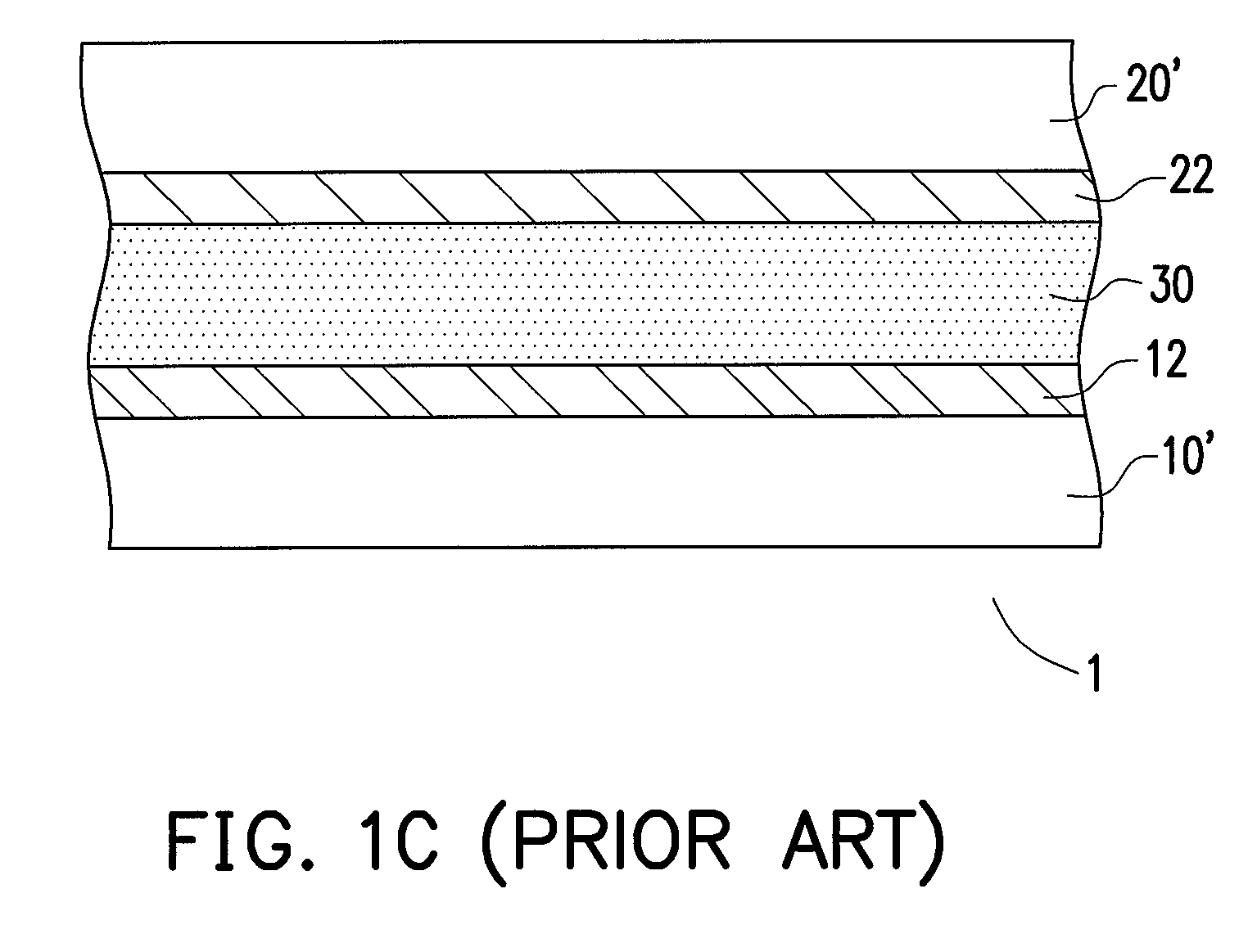
Now, the thinned glass substrates are liable to be cracked due to inadequate compressive strengths thereof.

Method used


Image

  • Manufacturing method of flexible display panel and manufacturing method of electro-optical apparatus
  • Manufacturing method of flexible display panel and manufacturing method of electro-optical apparatus
  • Manufacturing method of flexible display panel and manufacturing method of electro-optical apparatus

Examples


Embodiment Construction

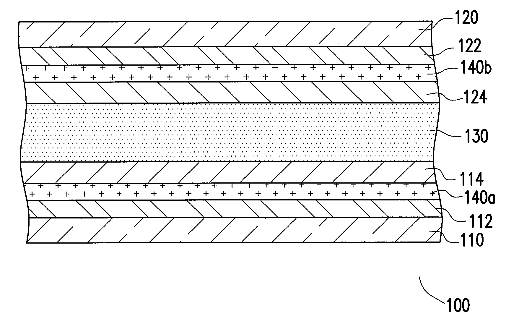
[0023]FIG. 2 is a cross-sectional view of a flexible display panel according to an embodiment of the present invention. Referring to FIG. 2, in the present embodiment, the flexible display panel 100 includes a first flexible substrate 110, a second flexible substrate 120 and a display media 130, wherein the display media 130 is disposed between the first flexible substrate 110 and the second flexible substrate 120.

[0024]In detail, a first etching stop layer 112 and an active layer 114 is disposed on the first flexible substrate 110, and a second etching stop layer 122 and a cover layer 124 are disposed on the second flexible substrate 120. Particularly, the first etching stop layer 112 is disposed between the active layer 114 and the first flexible substrate 110, and the second etching stop layer 122 is disposed between the cover layer 124 and the second flexible substrate 120. Moreover, the display media 130 is disposed between the active layer 114 of the first flexible substrate 1...


PUM

PropertyMeasurementUnit
fluorescentaaaaaaaaaa
weightaaaaaaaaaa
compressive strengthsaaaaaaaaaa

Abstract

A first etching stop layer and an active layer are formed on an inner surface of a first glass substrate, and a second etching stop layer and a cover layer are formed on an inner surface of a second glass substrate. A display media is formed between the first glass substrate and the second glass substrate. A first passivation layer is formed on an outer surface of the second glass substrate. A first etching process is performed to expose the first etching stop layer. A first flexible substrate is formed on the exposed first etching stop layer, and a second passivation layer is formed on the first flexible substrate. The first passivation layer is removed. A second etching process is performed to expose the second etching stop layer. A second flexible substrate is formed on the exposed second etching stop layer, and the second passivation layer is removed.

Description

CROSS-REFERENCE TO RELATED APPLICATION[0001]This application claims the priority benefit of Taiwan application serial no. 97132996, filed on Aug. 28, 2008. The entirety of the above-mentioned patent application is hereby incorporated by reference herein and made a part of this specification.BACKGROUND OF THE INVENTION[0002]1. Field of the Invention[0003]The present invention relates to a display panel and a fabricating method thereof, and an electro-optical device and a fabricating method thereof. More particularly, the present invention relates to a flexible display panel and a fabricating method thereof, and an electro-optical device and a fabricating method thereof.[0004]2. Description of Related Art[0005]With development of technology, techniques for display devices are developed accordingly, and flat panel displays (FPD) having features of lightness, slimness, shortness, and smallness gradually substitute conventional thick cathode ray tube (CRT) displays. Different types of th...

Claims


Application Information

Patent Timeline
Patent Type & Authority Patents(United States)
IPC IPC(8): B44C1/22
CPCG02F1/133305B32B2457/20Y02E10/549H10K59/873H10K59/123H10K50/844H10K77/111G02F1/136286G02F1/1368
Inventor CHWU, JONG-WENLIN, CHAO-CHENGWU, CHE-YAOLIU, YU-CHENYANG, WEI-CHIEH
Owner AU OPTRONICS CORP
Learn More