Optical scanning device and two-dimensional image display device using the same
a two-dimensional image and scanning device technology, applied in the direction of instruments, color television details, projectors, etc., can solve the problem of difficult to simply adopt the above-described prior art as a scanning mechanism, and achieve the effect of stable and uniform manner
- Summary
- Abstract
- Description
- Claims
- Application Information
AI Technical Summary
Benefits of technology
Problems solved by technology
Method used
Image
Examples
first embodiment
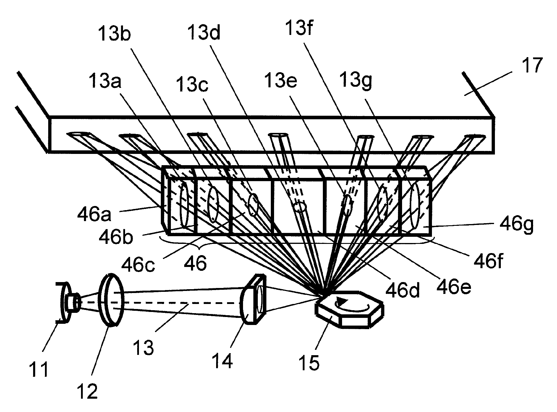
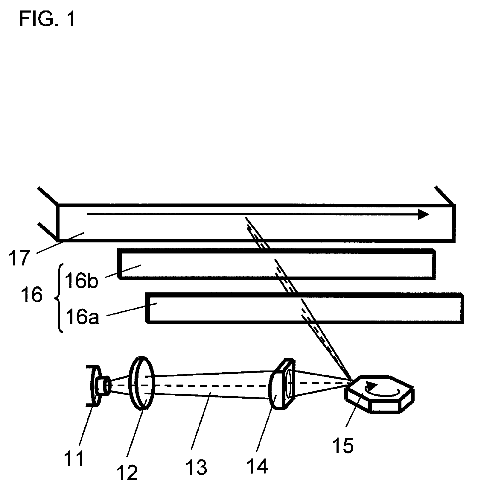
[0069]FIG. 1 is a diagram showing a configuration of an optical scanning device according to a first embodiment of the present invention. The optical scanning device according to the first embodiment includes a laser light source 11, a collimator lens 12, a cylindrical lens 14, a rotating polygon mirror 15, a scanning lens 16, and a light guide plate 17. The scanning lens 16 has a front cylindrical lens 16a and a rear cylindrical lens 16b.
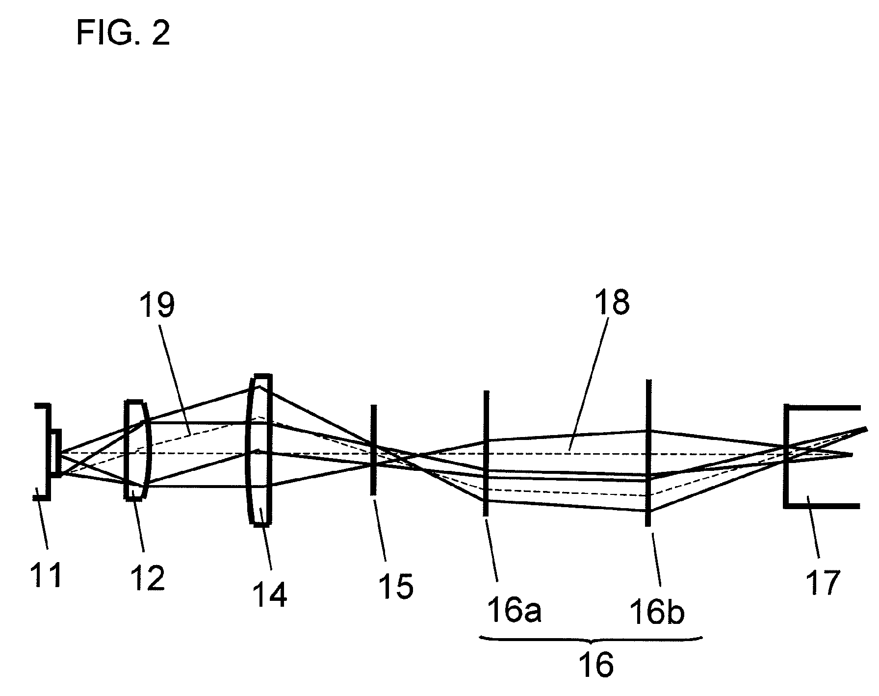
[0070]The laser light source 11 is a multi-mode fiber light source, in which a laser light 13 is guided through an optical fiber, not shown in the figure. The laser light 13 emitted from the multi-mode fiber light source 11 is, by the collimator lens 12, converted into a substantially parallel light in a thickness direction (a direction perpendicular to a scanning direction; the same shall apply hereinafter). The laser light 13, which has been converted into the substantially parallel light in the thickness direction, diverges at a divergence angl...
second embodiment
[0087]FIG. 5 is a diagram showing a configuration of an optical scanning device according to a second embodiment of the present invention. The optical scanning device according to the second embodiment includes a laser light source 11, a collimator lens 12, a cylindrical lens 14, a rotating polygon mirror 15, a scanning mirror 26, and a light guide plate 17. The scanning mirror 26 has a front scanning mirror 26a and a rear scanning mirror 26b.
[0088]FIG. 6 is a diagram showing a cross section, in a thickness direction, of a light propagation path in the optical scanning device shown in FIG. 5.
[0089]The optical scanning device according to the second embodiment differs from the above-described optical scanning device according to the first embodiment, in terms of the configuration of the scanning mirror 26. In addition, the laser light source 11 used in the second embodiment is not limited to a multi-mode fiber light source.
[0090]As described above, the present invention requires mer...
third embodiment
[0093]FIG. 7 is a diagram showing a configuration of an optical scanning device according to a third embodiment of the present invention. The optical scanning device according to the third embodiment includes a laser light source 11, a collimator lens 12, a cylindrical lens 14, a rotating polygon mirror 15, and a light guide plate 17.
[0094]FIG. 8 is a diagram showing a cross section, in a scanning direction, of a light propagation path in the optical scanning device shown in FIG. 7.
[0095]The configuration of the optical scanning device according to the third embodiment differs from the configurations of the optical scanning devices according to the first and second embodiments described above, in that the scanning lens 16 or the scanning mirror 26 is not provided. The collimator lens 12 and the cylindrical lens 14 are arranged so as to have curvatures in the scanning direction. In addition, the laser light source 11 used in the third embodiment is not limited to a multi-mode fiber l...
PUM
 Abstract
Description
Claims
Application Information
 - R&D
- Intellectual Property
- Life Sciences
- Materials
- Tech Scout
- Unparalleled Data Quality
- Higher Quality Content
- 60% Fewer Hallucinations
Browse by: Latest US Patents, China's latest patents, Technical Efficacy Thesaurus, Application Domain, Technology Topic, Popular Technical Reports.
© 2025 PatSnap. All rights reserved.Legal|Privacy policy|Modern Slavery Act Transparency Statement|Sitemap|About US| Contact US: help@patsnap.com


