Optical scanning device and two-dimensional image display device using the same

Inactive Publication Date: 2010-05-06
PANASONIC CORP
View PDF3 Cites 15 Cited by
  • Summary
  • Abstract
  • Description
  • Claims
  • Application Information

AI Technical Summary

Benefits of technology

[0020]According to the present invention described above, an exit pupil, which requires an accuracy of merely a few millimeter order, is formed on a side surface of a light gu

Problems solved by technology

On the other hand, in a case where a laser light source is used to uniformly irradiate an entire liquid crystal panel with a light from the rear su

Method used


Image

  • Optical scanning device and two-dimensional image display device using the same
  • Optical scanning device and two-dimensional image display device using the same
  • Optical scanning device and two-dimensional image display device using the same

Examples


first embodiment

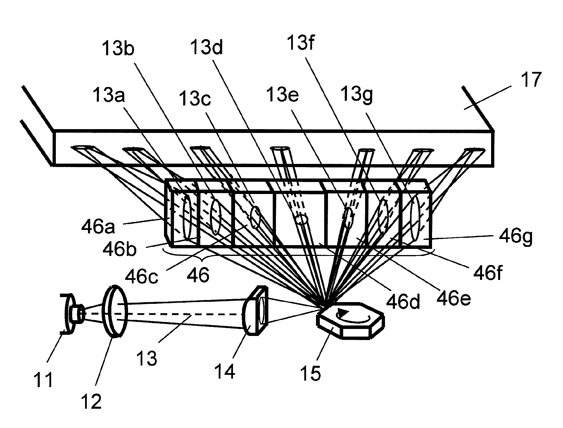
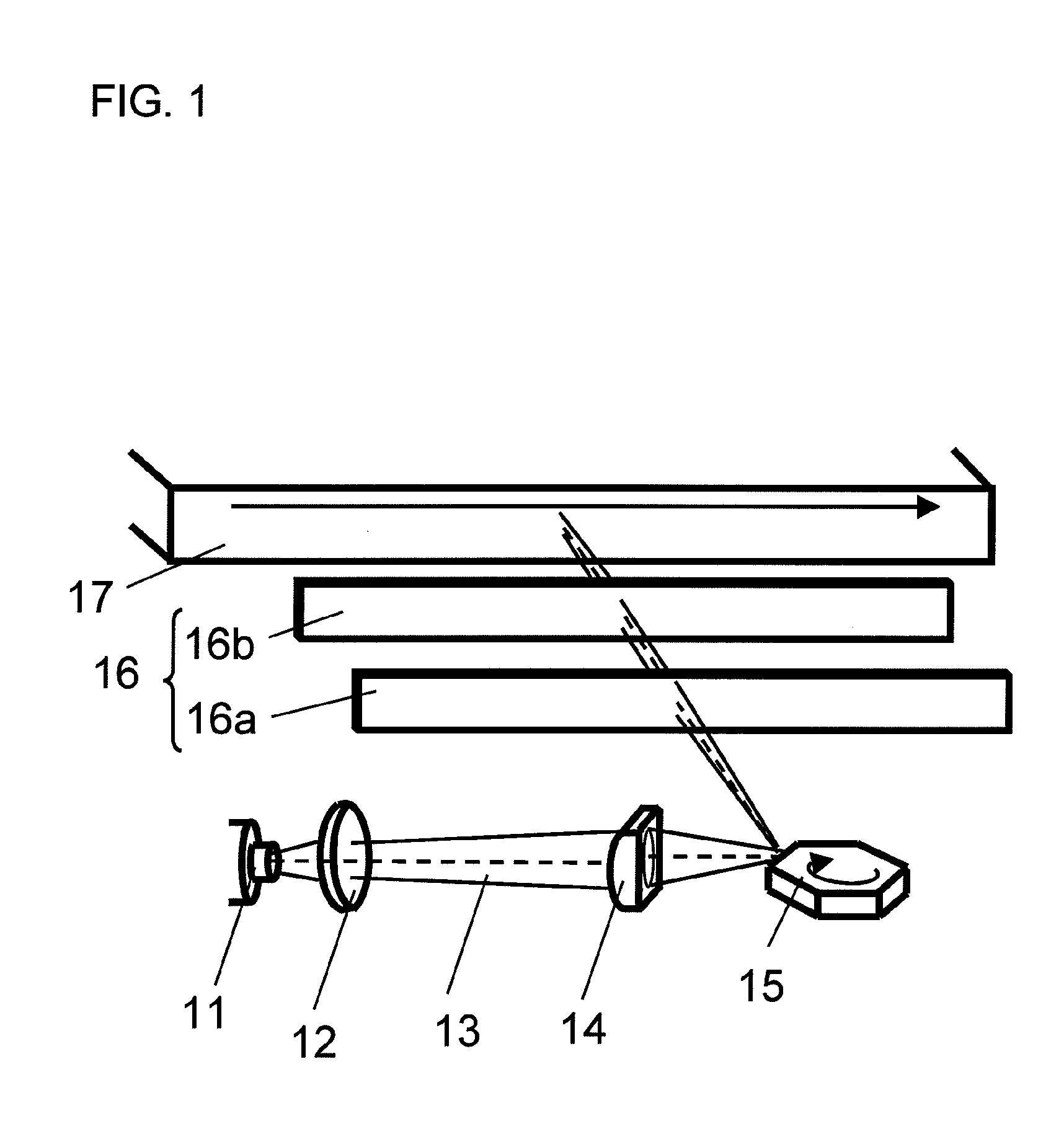
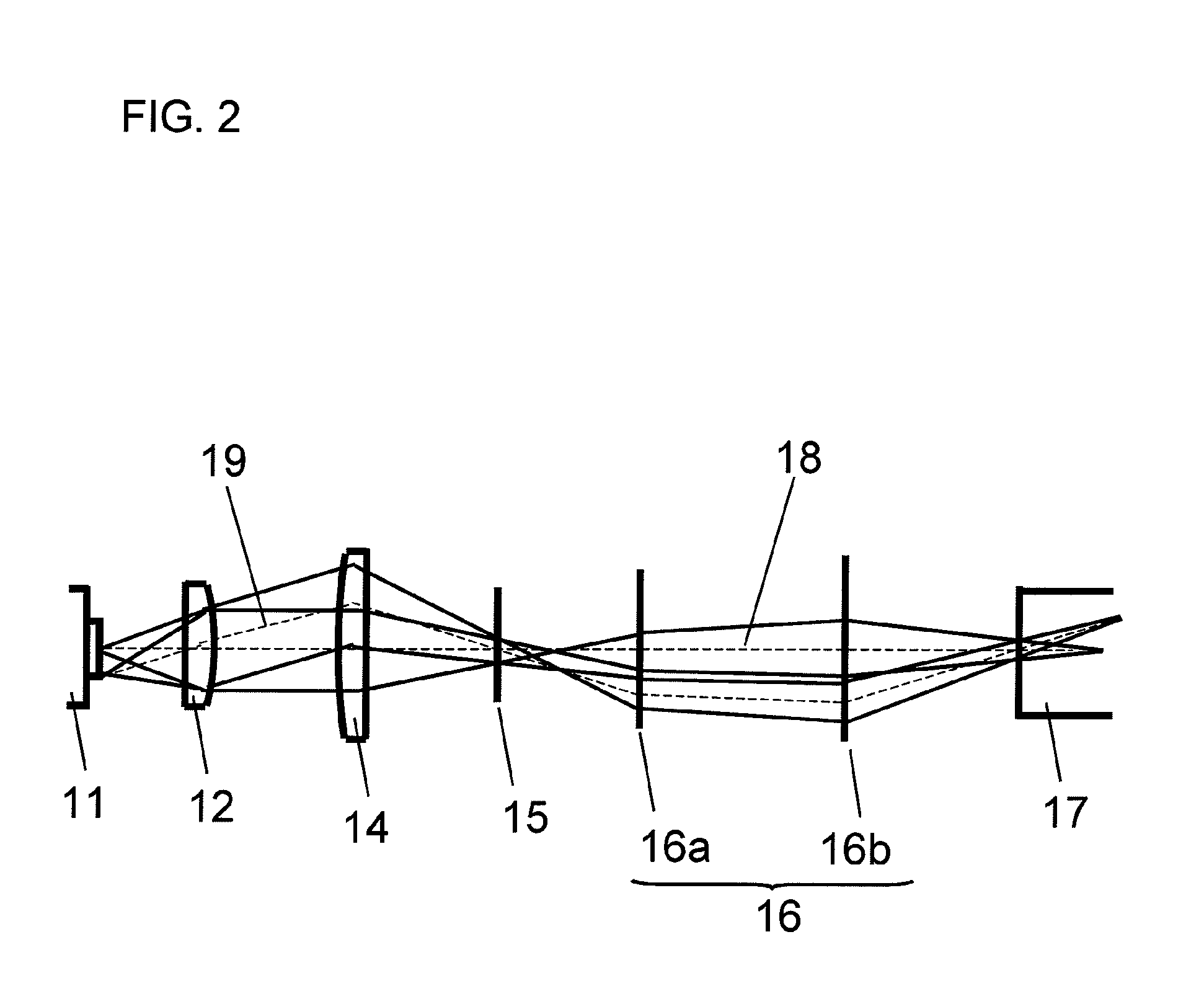
[0067]FIG. 1 is a diagram showing a configuration of an optical scanning device according to a first embodiment of the present invention. The optical scanning device according to the first embodiment includes a laser light source 11, a collimator lens 12, a cylindrical lens 14, a rotating polygon mirror 15, a scanning lens 16, and a light guide plate 17. The scanning lens 16 has a front cylindrical lens 16a and a rear cylindrical lens 16b.

[0068]The laser light source 11 is a multi-mode fiber light source, in which a laser light 13 is guided through an optical fiber, not shown in the figure. The laser light 13 emitted from the multi-mode fiber light source 11 is, by the collimator lens 12, converted into a substantially parallel light in a thickness direction (a direction perpendicular to a scanning direction; the same shall apply hereinafter). The laser light 13, which has been converted into the substantially parallel light in the thickness direction, diverges at a divergence angl...

second embodiment

[0085]FIG. 5 is a diagram showing a configuration of an optical scanning device according to a second embodiment of the present invention. The optical scanning device according to the second embodiment includes a laser light source 11, a collimator lens 12, a cylindrical lens 14, a rotating polygon mirror 15, a scanning mirror 26, and a light guide plate 17. The scanning mirror 26 has a front scanning mirror 26a and a rear scanning mirror 26b.

[0086]FIG. 6 is a diagram showing a cross section, in a thickness direction, of a light propagation path in the optical scanning device shown in FIG. 5.

[0087]The optical scanning device according to the second embodiment differs from the above-described optical scanning device according to the first embodiment, in terms of the configuration of the scanning mirror 26. In addition, the laser light source 11 used in the second embodiment is not limited to a multi-mode fiber light source.

[0088]As described above, the present invention requires mer...

third embodiment

[0091]FIG. 7 is a diagram showing a configuration of an optical scanning device according to a third embodiment of the present invention. The optical scanning device according to the second embodiment includes a laser light source 11, a collimator lens 12, a cylindrical lens 14, a rotating polygon mirror 15, and a light guide plate 17.

[0092]FIG. 8 is a diagram showing a cross section, in a scanning direction, of a light propagation path in the optical scanning device shown in FIG. 7.

[0093]The configuration of the optical scanning device according to the third embodiment differs from the configurations of the optical scanning devices according to the first and second embodiments described above, in that the scanning lens 16 or the scanning mirror 26 is not provided. The collimator lens 12 and the cylindrical lens 14 are arranged so as to have curvatures in the scanning direction. In addition, the laser light source 11 used in the third embodiment is not limited to a multi-mode fiber ...


PUM


Abstract

An optical scanning device capable of stably and uniformly performing linear optical scanning by using a high-brightness light source is provided. The device includes: at least one laser light source (11) for emitting a laser light; a deflection section (15) for deflecting and scanning the laser light emitted from the at least one laser light source (11); and a light guide plate (17) of which a side surface is irradiated with the laser light deflected and scanned by the deflection section (15). The at least one laser light source (11) includes a multi-mode fiber light source, or a broad-stripe semiconductor laser light source arranged such that a vertical direction of a stripe structure is parallel to a scanning direction. An exit pupil in a thickness direction, which is perpendicular to the scanning direction, is formed at least in one area on the side surface of the light guide plate (17).

Description

TECHNICAL FIELD[0001]The present invention relates to an optical scanning device using a laser light source having mainly three colors (R, G, B), for use in a two-dimensional image display device such as a liquid crystal display device or the like.BACKGROUND ART[0002]A display device includes a light-emitting display device such as an organic light-emitting display device and a plasma display device, and a light-receiving display device such as a liquid crystal display device. The light-emitting display device self-emits a light. The light-receiving display device cannot self-emit a light and therefore requires a separate light source. A general liquid crystal display device includes two display panels which are provided with electric field generating electrodes, and a liquid crystal layer which has dielectric anisotropy and is interposed between the two liquid crystal panels. Voltage is applied to the electric field generating electrode, to thereby generate an electric field in the...

Claims


Application Information

Patent Timeline
IPC IPC(8): G02B26/12G02B26/10
CPCG02B26/123G03B33/08H04N9/3129
Inventor SHIKII, SHINICHIITOH, TATSUOYAMAMOTO, KAZUHISAKADOWAKI, SHINICHI
Owner PANASONIC CORP
Why Eureka
Try Eureka