Nuclear Emergency Multifunctional Operation Robot

a multi-functional, nuclear technology, applied in the direction of manipulators, gripping heads, program-controlled manipulators, etc., can solve the problems of unfavorable robot size minimization and stability, too high pedestals, and no nuclear emergency robot on the market that meets the above design needs

Pending Publication Date: 2022-03-10
NANHUA UNIV
View PDF0 Cites 8 Cited by
  • Summary
  • Abstract
  • Description
  • Claims
  • Application Information

AI Technical Summary

Benefits of technology

[0010]The present disclosure aims to overcome the shortcomings in the existing technology, and provides a nuclear emergency multifunctional operation robot, which fully meets the requirements of a nuclear emergency robot for size miniaturization, folding performance, ground clearance height of pedestal, obstacle crossing performance, and quick switching of operations among multiple types of work.

Problems solved by technology

The radiation resistance of electrical components involved in the emergency robots for the nuclear power plants, the radiation resistance of robot systems, the system reliability, and the functional diversification are all key and difficult points in the design of the emergency robots.
In an emergency case of a nuclear power plant, accidents that occur in a nuclear radiation environment have a greater radiation risk, and nuclear emergency robots are especially required to participate in various rescue tasks.
1. Due to the limitation of entrance and passage sizes on site, the miniaturization and folding performance of the robot must be considered to facilitate safe passage through a narrow space.
2. A ground clearance height of a pedestal should not be too low or too high. A too low pedestal is easily scratched by debris on the ground, and a too high pedestal is unfavorable for the size minimization and stability of the robots.
3. In order to meet the needs of complex site facilities and the surrounding environment in the nuclear power plant, the robot should have the ability to cross an obstacle, climb slopes and quickly switch operations among multiple types of work.
R&D personnel have been committed all along to the research and development of nuclear emergency robot systems that meet the above needs, but there is currently no nuclear emergency robot on the market that meets the above design needs.
The abutting and separating steps are simple and quick, and have low accuracy requirements.

Method used


Image

  • Nuclear Emergency Multifunctional Operation Robot
  • Nuclear Emergency Multifunctional Operation Robot
  • Nuclear Emergency Multifunctional Operation Robot

Examples


embodiment 1

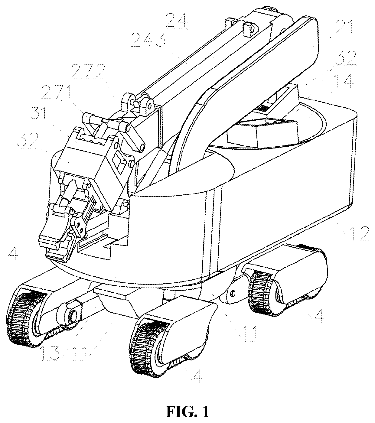
[0076]As shown in FIG. 1 to FIG. 20, a nuclear emergency multifunctional operation robot includes a base, a mechanical arm, a tool change-over device, and motion supporting devices 4.

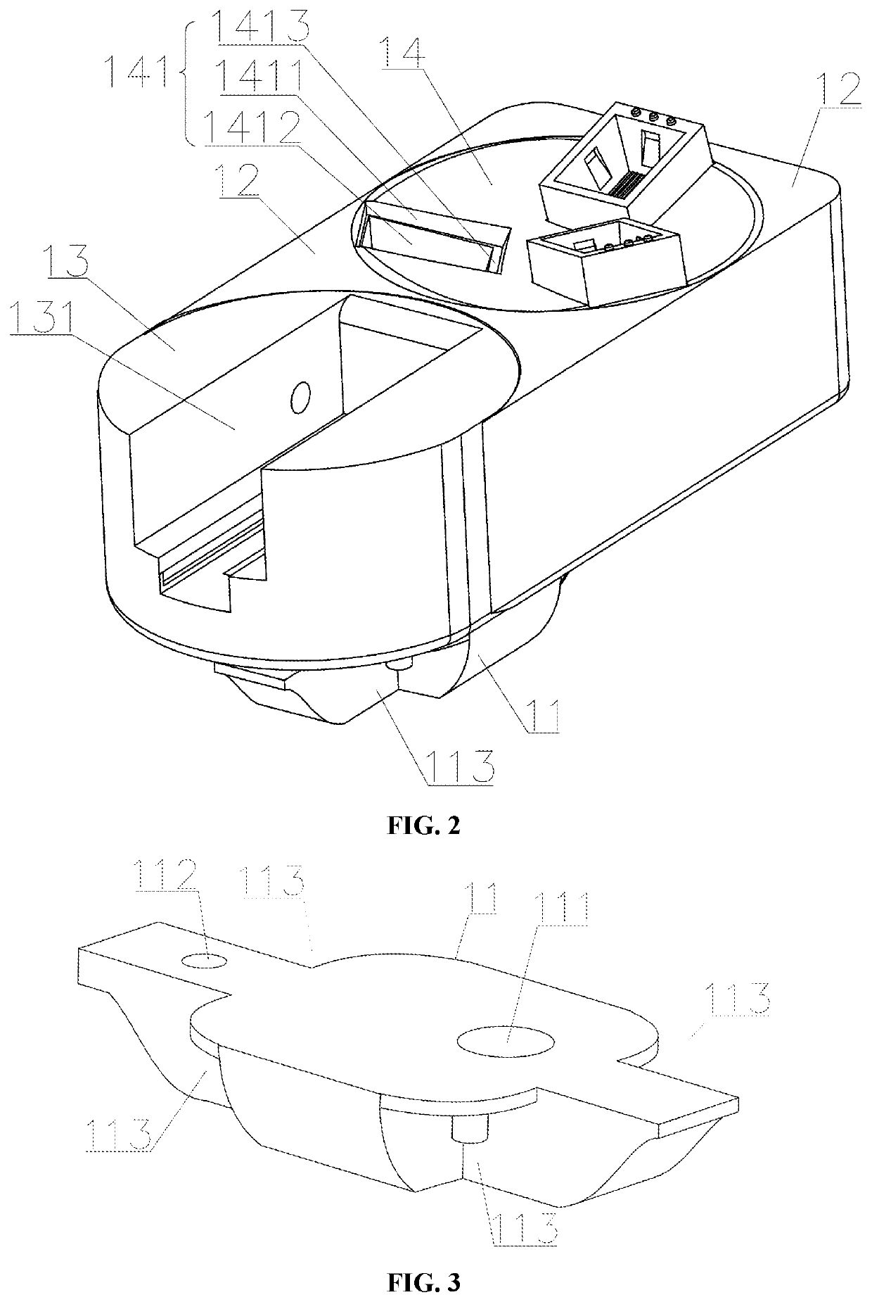
[0077]The base includes a pedestal 11, a mounting seat A 12, a mounting seat B 13, a mounting seat C 14, a rotation driving mechanism A, and a rotation driving mechanism B.

[0078]A motor mounting hole A 111 and a motor mounting hole B 112 are formed in the pedestal 11; both sides of the front end and both sides of the rear end of the pedestal 11 are respectively provided with mounting gaps 113 A used to mounting the motion supporting devices.

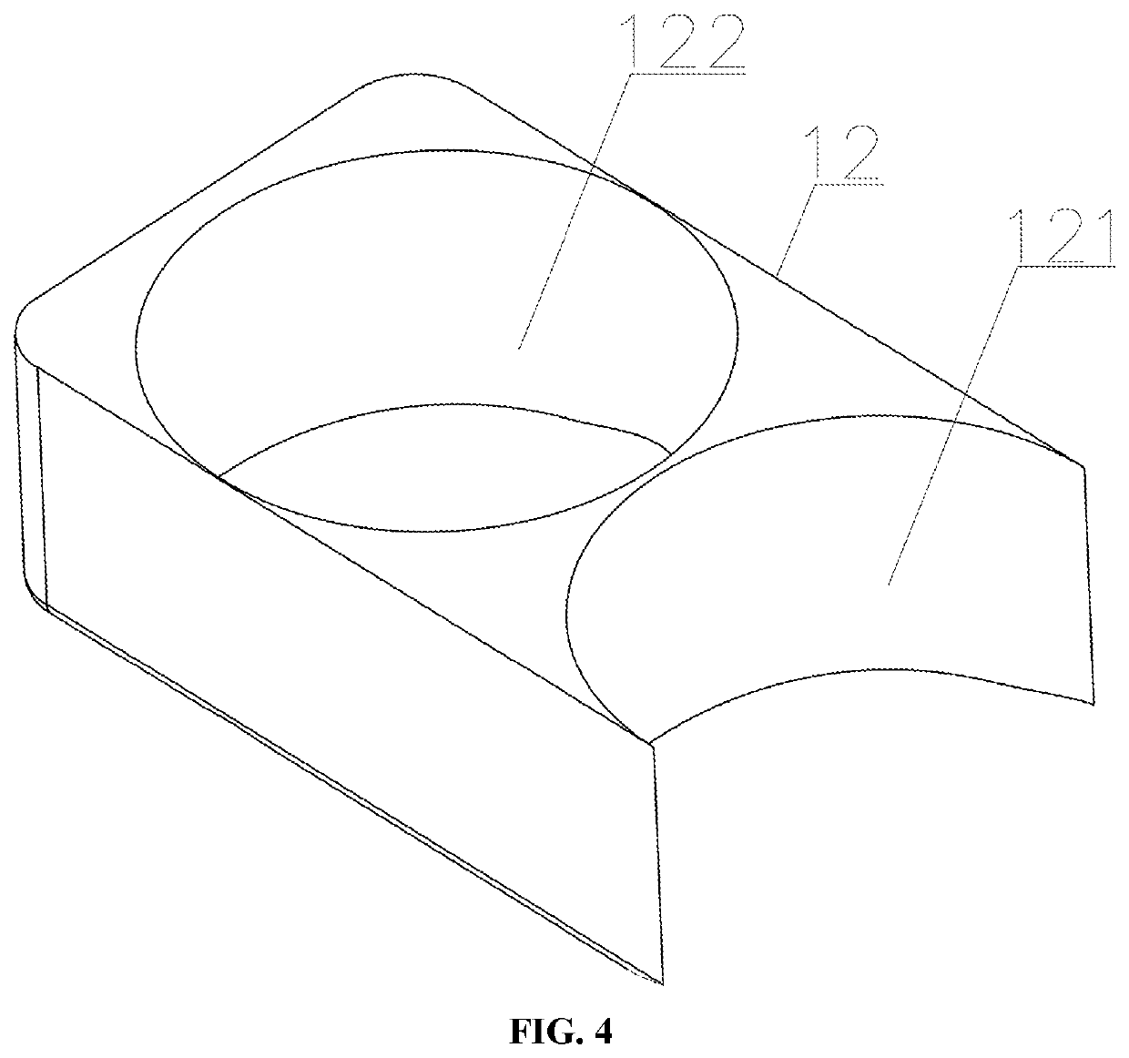
[0079]The mounting seat A 12 is fixedly mounted at the upper end of the pedestal 11, and the front and rear ends of the mounting seat A are respectively provided with a front mounting region 121 and a rear mounting region 122; the front mounting region 121 is an arc-shaped gap formed in the front end of the mounting seat A 12 and running through the mounting seat A 1...


PUM


Abstract

A nuclear emergency multifunctional operation robot includes a base, a mechanical arm, a tool change-over device, and motion supporting devices. The base includes a pedestal, a mounting seat A, a mounting seat B, a mounting seat C, a rotation driving mechanism A, and a rotation driving mechanism B. The front end of the mechanical arm is connected to the mounting seat B; the tool change-over device includes a male connector and a female connector which are abutted with or separated from each other; and the motion supporting devices are used to drive the nuclear emergency multifunctional operation robot to move. The present disclosure has the advantages that the base can be integrated with various end tools, so that the operation robot conveniently changes over tools according to operation needs to conduct various types of operations.

Description

CROSS REFERENCE TO RELATED APPLICATION(S)[0001]This patent application claims the benefit and priority of Chinese Patent Application No. 202010942668.3, filed on Sep. 9, 2020, the disclosure of which is incorporated by reference herein in its entirety as part of the present application.TECHNICAL FIELD[0002]The present disclosure relates to the technical field of nuclear emergency equipment, in particular, a nuclear emergency multifunctional operation robot.BACKGROUND ART[0003]With the rapid development of the nuclear power industry, the requirements for nuclear safety are also increasing day by day, and the need for the research and development of emergency response robots for nuclear power plants has gradually become prominent. The radiation resistance of electrical components involved in the emergency robots for the nuclear power plants, the radiation resistance of robot systems, the system reliability, and the functional diversification are all key and difficult points in the des...

Claims


Application Information

Patent Timeline
Patent Type & Authority Applications(United States)
IPC IPC(8): B25J9/00B25J9/10B25J9/14B25J9/16B25J13/08B25J19/00B25J5/00
CPCB25J9/0009B25J9/102B25J9/144B25J5/005B25J13/086B25J19/0025B25J9/1697B25J5/00B25J11/00B25J9/08B25J18/00B25J19/00B62D55/065B25J15/0408B25J9/045B62D57/028B25J9/1612
Inventor TANG, DEWENZOU, SHULIANGWANG, WEIXIAO, WEIWEIZHANG, DELIU, JUNDENG, QIAN
Owner NANHUA UNIV
Why Eureka
Try Eureka