Display device

a display device and display technology, applied in the field of display devices, can solve the problems of not being able to form impressive images such as those that are partially made stereoscopic, and the real image cannot be superimposed, and the resultant image is not impressiv

Active Publication Date: 2012-10-30
STANLEY ELECTRIC CO LTD
View PDF4 Cites 9 Cited by
  • Summary
  • Abstract
  • Description
  • Claims
  • Application Information

AI Technical Summary

Benefits of technology

[0012]In view of the above-mentioned problems, an object of the present invention is to provide a display device capable of freely setting a viewpoint (angle) from which an image formed by an imaging optical system of real specular image is seen.
[0016]Variation of the positional relationship thereamong with time results in change of the position of a floating image with time. Specifically, if the object is moved along a line connecting the object and the imaging optical system of real specular image, an image may be formed at various positions. Accordingly, an image to be formed by the first half mirror surface may gradually be changed from a completely virtual image to a completely real image, thereby making an image to be seen more impressive.
[0023]A shape of the optical hole should be considered, wherein all of the adjacent inner wall surfaces are orthogonal, as in a cube or a rectangular parallelepiped. In such a case, the gaps between adjacent dihedral corner reflectors can be minimized, and thereby highly dense arrangements are possible. It is preferable that reflection be prevented by a surface other than that of a dihedral corner reflector that faces an object of view.
[0024]In the case where a dihedral corner reflector has a plurality of inner mirror surfaces, some of the transmitted light may undergo multiple reflections, i.e., there may occur multiple reflections of light beams passing through the hole several times or more than that of assumed reflections. Regarding countermeasures for these multiple reflections, if two mutually orthogonal mirror surfaces are formed on the inner wall of an optical hole, such multiple reflection is prevented in the following ways. In one way, a surface other than these two mirror surfaces may be made non-specular to prevent reflection of light beams by this surface. In another way, a surface other than these mirror surfaces may be tilted from an element surface so that it may not orthogonal to the element surface, or may be curved. In either way, generation of the multiply reflected light beam reflected three times or more may be reduced, or prevented. In order to form a non-specular surface, the following configuration may be used in which a target surface may be coated with an anti-reflection coating or a thin film and, alternatively, the surface roughness of the target surface may be increased to cause diffuse reflection on the target surface. In addition, the existence of a transparent and flat substrate does not obstruct the functions of the optical element, and therefore any appropriate substrate may be used as a supporting member and / or a protective member.
[0025]In order to enhance the brightness level of a real image to be projected, it is desirable that a number of dihedral corner reflectors arranged on an element surface are as close as possible to each other. As an example, lattice arrangement of the dihedral corner reflectors is effective. Such an arrangement makes it easy to manufacture a display device, as a merit. Amirror surface of each dihedral corner reflector may be a flat surface for causing reflection of light beams, and which is made of a lustrous substance such as metal or resin, regardless of whether the substance is solid or liquid. A mirror surface of a dihedral corner reflector may also be such that it causes reflection or total reflection at a flat boundary interface between transparent media of different refractive indexes. In the case where a total internal reflection is used for the mirror surface, it is highly likely that the undesirable multiple reflections by the plurality of multiple mirror surfaces will exceed the critical angle of the total internal reflection, and therefore it is expected that these undesirable multiple reflections will naturally be suppressed. Additionally, the mirror surface may either be formed only on a limited part of the inner wall of an optical hole, or may be constructed of a plurality of unit mirror surfaces arranged in parallel, as long as each mirror surface serves its function without problems. Regarding the latter aspect, in other words, the formation of a mirror surface from unit mirror surfaces means that a mirror surface may be divided into a plurality of unit mirror surfaces. In this case, the unit mirror surfaces are not necessarily required to exist on the same plane, but are parallel. Furthermore, the unit mirror surfaces may be contact with each other, or may be spaced from each other.

Problems solved by technology

This means that an indication on the display part on the back wall and a real image cannot be superimposed when seen by the viewer.
Furthermore, the imaging optical system of real specular image can only form real images, meaning that an impressive image such as the one that is partially made stereoscopic cannot be formed.
Accordingly, except for being a floating image, the resultant image is not impressive.

Method used


Image

  • Display device
  • Display device
  • Display device

Examples


Embodiment Construction

[0045]A display device of an embodiment according to the present invention will be described herein below by referring to the drawings.

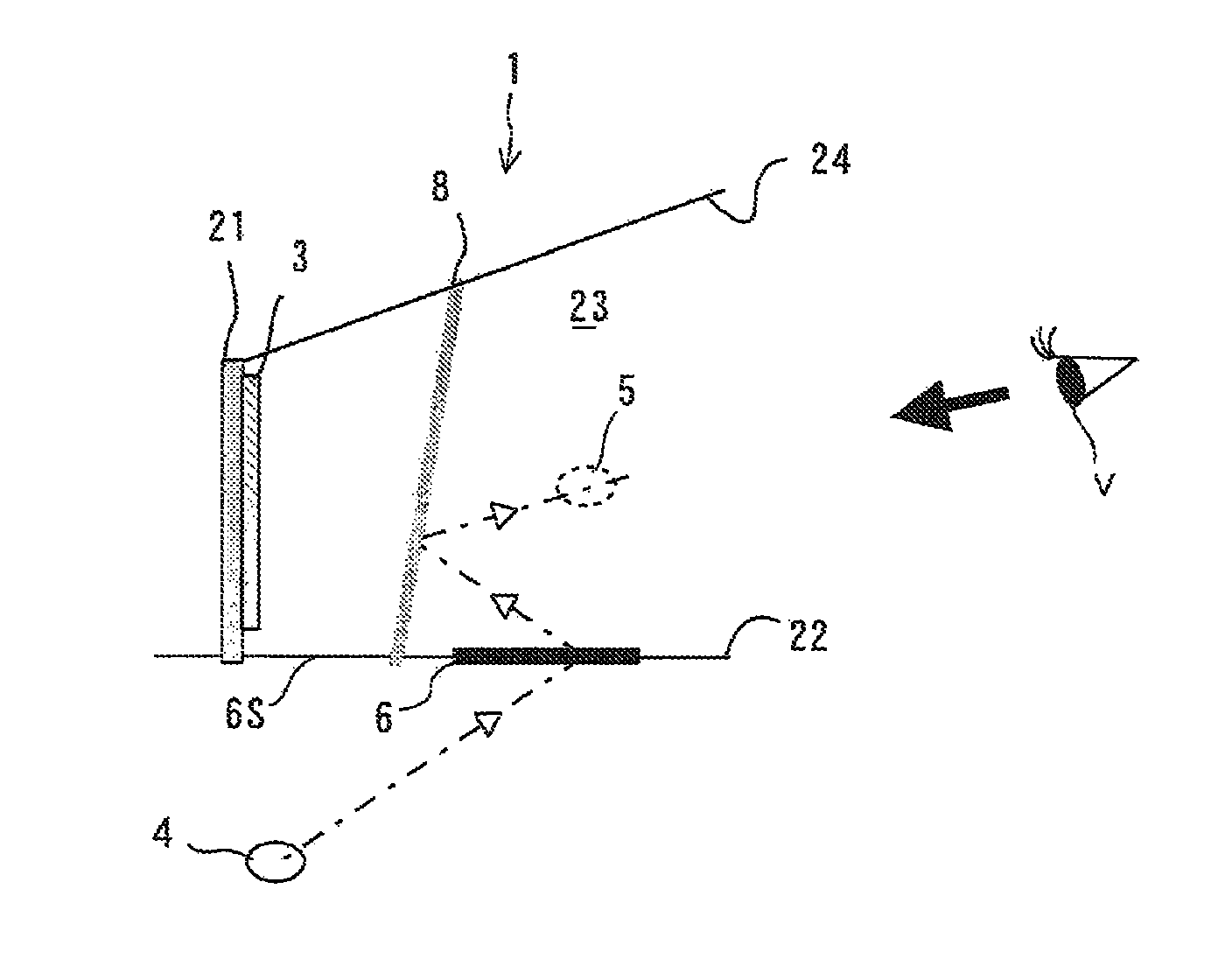
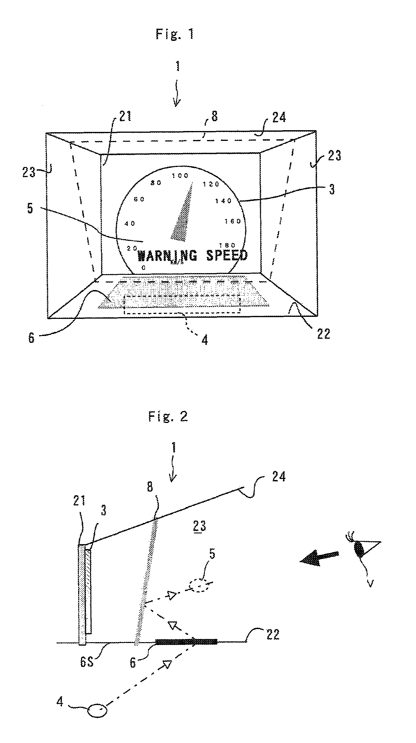
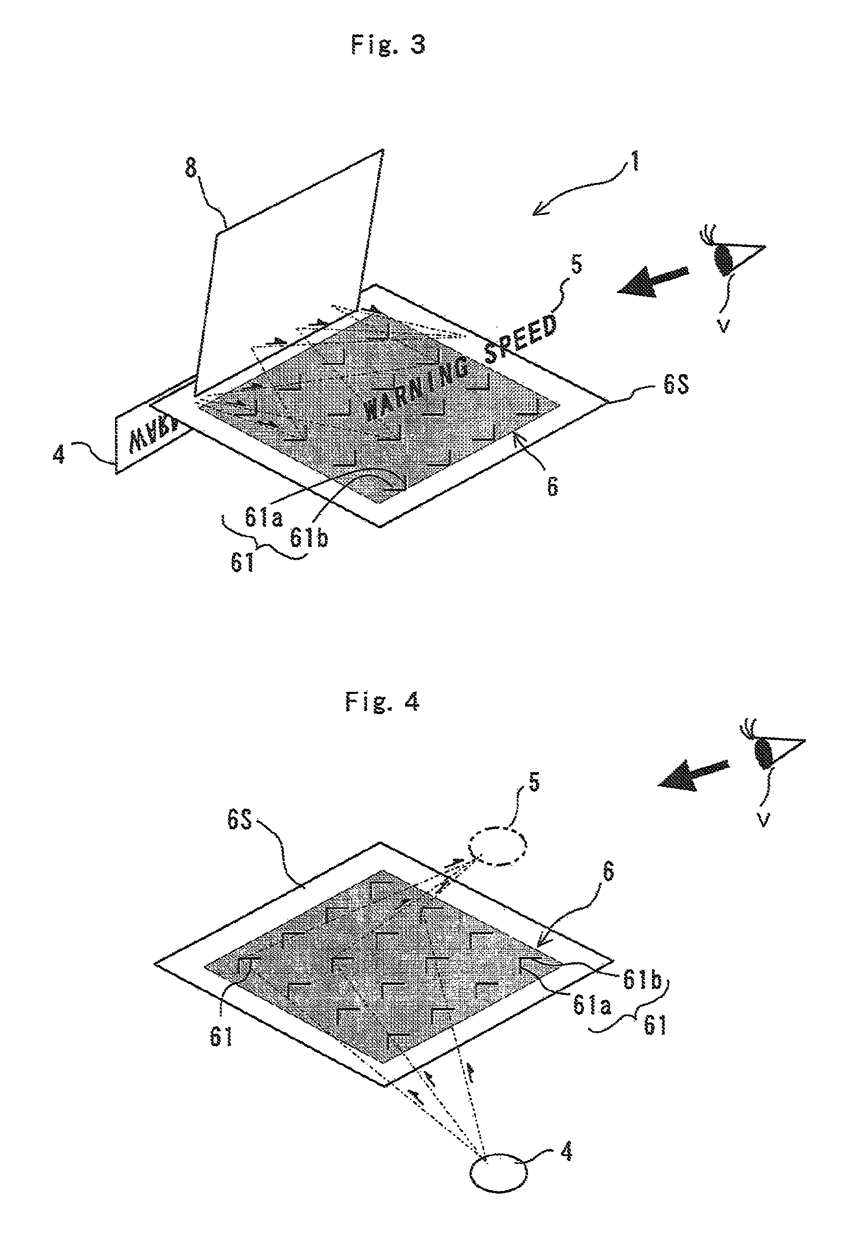
[0046]FIG. 1 is a schematic front view illustrating an instrument panel of a vehicle such as an automobile and its surroundings including a display device 1 of the embodiment of the present invention. FIGS. 2 and 3 are schematic sectional and perspective views respectively that explain the operation of the display device 1.

[0047]The display device 1 is made by applying the present invention to an instrument panel and to its surroundings on the driver's side of a transportation machine such as an automobile. Specifically, as shown in FIG. 2, the display device 1 includes a back wall 21 farthest from the viewpoint of a driver as a viewer V, a bottom wall 22, right and left side walls 23, and an upper wall 24 connecting to the back wall 21 and arranged to surround a space in front of the back wall 21 when viewed from the driver, and a display area 3 as ...


PUM


Abstract

A display device includes: a display part containing a first display region visually recognized by a viewer; an object of view arranged in a second display region; an imaging optical system of real specular image for defining a first space in which the first display region exists and a second space in which the second display region exists, the imaging optical system of real specular image including a semitransparent substrate with a plane of symmetry, the imaging optical system of real specular image forming a real image of the object of view in the first space of the first display region with light passing through the substrate; and a half mirror arranged in the first space of the first display region, the half mirror reflecting light beams emitted from the imaging optical system of real specular image to guide the reflected light beams to the viewer, while allowing an image formed in the first display region to be seen by the viewer.

Description

[0001]This application claims the priority benefit under 35 U.S.C. §119 of Japanese Patent Application No. 2009-222341 filed on Sep. 28, 2009, which is hereby incorporated in its entirety by reference.BACKGROUND OF THE INVENTION[0002]1. Field of the Invention[0003]The present invention relates to a display device for allowing a viewer to see a real image of an object of view formed in the air by using an imaging optical system of real specular image.[0004]2. Description of the Related Art[0005]A display device is suggested (see WO2007 / 116639), in which a viewer is allowed to see a real image of an object of view, i.e., real specular image formed in the air by using an imaging optical system of real specular image.[0006]This display device includes an object of view arranged in a space opposite to a viewer, and an imaging optical system of real specular image for forming a real image of the object of view in a space in which the viewer exists. A real image of the object is formed at ...

Claims


Application Information

Patent Timeline
Patent Type & Authority Patents(United States)
IPC IPC(8): G02B27/14
CPCG02B5/124G02B27/0101G02B2027/0123
Inventor SUGIYAMA, TAKASHI
Owner STANLEY ELECTRIC CO LTD
Why Eureka
Try Eureka