Scraper structure

a technology of a scraper and a spherical structure, which is applied in the field of scraper structure, can solve the problems of b> jumping off during scraping work, affecting the scraping effect, and causing the blade to fall off, so as to achieve quick replacement, strong scraping and cleaning, and safe and firm grip

Inactive Publication Date: 2012-11-06
LIN WEN CHEN
View PDF26 Cites 4 Cited by
  • Summary
  • Abstract
  • Description
  • Claims
  • Application Information

AI Technical Summary

Benefits of technology

[0009]Thus, the objective for the invention is to provide a scraper structure that primarily has a jaw groove at the bottom surface of the scraping section of a scraper to connect to the blade slot. In the back end of the jaw groove there is a round hole passing to the top surface of the scraping section. A jaw plate has a clamp jaw in the front and a round hole in the back. When the jaw plate is installed inside the jaw groove at the bottom of the scraping section by a passing fastener, a fastening button is provided at the top surface of the scraping section to be combined with the fastener. This enables tightening force provided to the center of the jaw plate and great pressing force to the blade by the clamp jaw in the front. This will achieve quick replacement and stable assembly for the blade.
[0010]Another objective for the invention is to provide a scraper structure, in which the fastening button it uses to combine the fastener can be a spherical object on the top surface of the scraping section, and moreover can assure safe and firm grip by the front hand of a user to achieve powerful scraping and cleaning.
[0011]To achieve the above objectives, a scraper structure is provided in the invention and mainly comprised of a long handle and a scraping section. The scraping section is coupled with the front of the long handle. The front end of the scraping section extends downward or forward to form a blade slot, while its bottom has a jaw groove to connect to the blade slot. A round hole on the inner rear side of the jaw groove is provided to pass through to the top of the scraping section. Associated with the round hole there is a square groove on the inner side of the jaw groove. A jaw plate with similar shape to the jaw groove of the scraping section has a clamp jaw in the front to match the orientation of the blade slot, while in the rear end there is a square hole. The jaw plate is installed inside the jaw groove of the scraping section by a passing fastener. When a fastening button on the top of the scraping section is combined with the fastener, the fastener can provide tightening force with the jaw plate aiming the rear end and allows the clamp jaw in the front to exert a huge pressure onto the blade. This also enables firm lock of the blade into the blades lot of the scraping section. On the other hand, if the fastening button is loosened, the fastener will lose tightening force and quick replacement of blade will be achievable. In the rear end of the long handle a grip is provided for the user to grasp and exert force. Inside the grip, there is a turn cap and a chamber for storing the blade and facilitating replacement.DETAILED DESCRIPTION OF THE PREFERRED EMBODIMENT
[0016]Please refer to FIG. 4 for another embodiment for the jaw plate for the invention. The jaw plate 31 is located at the side of the square hole 39 and can be equipped with ribs 311 extendable to the front clamp jaw 38. The purpose is to enhance the grip of the blade 32 by the clamp jaw 38 and strengthen the assembly in the blade slot 35.

Problems solved by technology

First, the tightening mechanism for the clamp jaw 15 inside the jaw base 13 of the scraping section 11 is achieved by passing the screw 17 through the clamp jaw 15 and the scraping section 11. The passing screw 17 needs to be able to exert even tightening force, which is only achievable by at least three screws 17. In other words, it needs to loosen and tighten at least three screws 17 for replacing the blade 16. It is obviously inconvenient.
Second, since the clamp jaw 15 uses the passing screw 17 to achieve tightening the blade 16 and the blade 16 location is very close to the tightening screw 17, when the tightening force by any screw 17 is insufficient, there is a potential risk of the blade 16 jumping off during scraping work and subject to counterforce. It could be an unstable assembly.
Third, the blade 16 is horizontally installed in the front end of the scraping section 11. When a user grasps the long handle with two hands to remove the residues on object surface by the blade 16, the angle between the scraping section 11 and object surface is very small. Therefore, the hand grasping the front end of the long handle 10 becomes very close to the object surface. There is a potential risk of injury to the fingers of the griping hand if caution is not applied.

Method used


Image

  • Scraper structure
  • Scraper structure
  • Scraper structure

Examples


Embodiment Construction

[0012]The following describes the features for the invention with a preferred embodiment and figures.

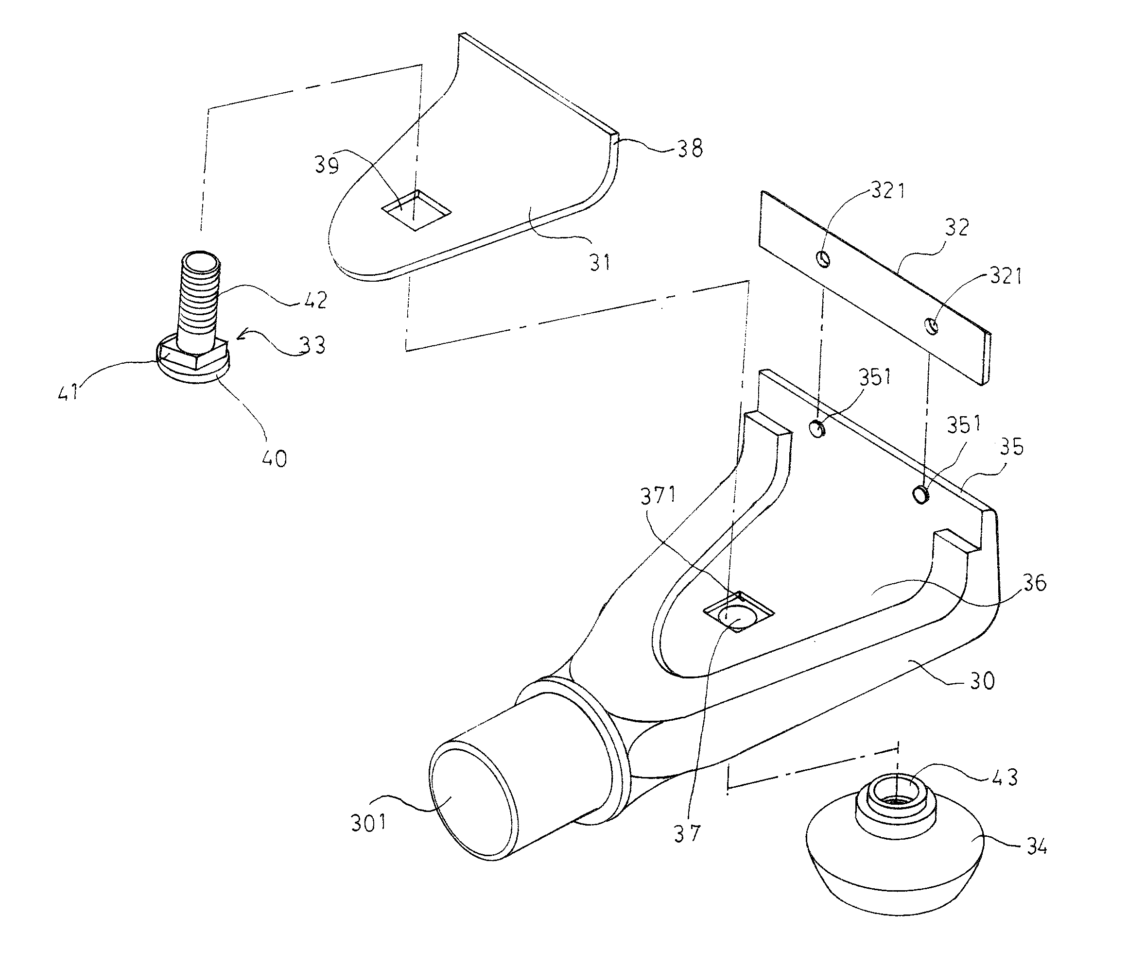
[0013]Please refer to FIG. 3, FIG. 4 and FIG. 5 for the structural disassembly diagram and assembly diagram for the scraper in the invention. The scraper is generally comprised of a long handle 20 for handgrip and a scraping section 30 in its front.

[0014]The long handle 20 has a grip 21 in the rear end and outer side for handgrip, which inside contains a chamber 22 and a turn cap 23 for storing the blade 32 and facilitating replacement. Its front end has a connection groove 24 that can be assembled with the rear end coupler 301 of the scraping section 30.

[0015]The scraping section 30 is comprised of a jaw plate 31, a blade 32, a fastener 33 and a fastening button 34. The front end of the scraping section extends downward to form a blade slot 35, which inner side has two connection pins 351 at predetermined locations. At the corresponding locations on the blade 32 there are two connec...


PUM


Abstract

The invention relates to a scraper structure, which is generally comprised of a long handle for handgrip and a scraping section in its front. Basically, the scraping section of the scraper is comprised of a jaw plate, a blade, a fastener and a fastening button. The front end of the scraping section extends downward or forward to form a blade slot and has a jaw base at the bottom to connect to the blade slot. The jaw plate has identical shape to the clamp jaw in the front of the jaw base. The fastener and the fastening button are combined to provide tightening and enable the clamp jaw in the front of the jaw plate to exert great pressure onto the blade and achieve quick blade replacement and assembly. Further, the fastening button can exert more force by the front hand in grasping the handle and achieve powerful scraping.

Description

BACKGROUND OF THE INVENTION[0001]1. Field of the Invention[0002]The invention relates to a tool to remove the residues on object surface in an improvement and remodeling project. Especially it relates to a scraper structure, which provides primarily quick replacement and stable assembly for scraper blade and further a front handle to facilitate the operation with more power and attain effective cleaning.[0003]2. Description of the Prior Art[0004]To replace wallpaper or carpet in interior remodeling, it is necessary to remove the residual adhesive on objective surface to assure the flatness. Please refer to FIG. 1 and FIG. 2 for the structural disassembly diagram and assembly diagram for a common scraper. The scraper is generally comprised of a long handle 10 for handgrip and a scraping section 11 in its front. The rear end of the scraping section 11 has a connection end 12 for connection with the long handle 10, while the front end has a jaw base 13 and a blade slot 14 for assembly ...

Claims


Application Information

Patent Timeline
Patent Type & Authority Patents(United States)
IPC IPC(8): B26B3/00
CPCA47L13/08E04G23/006
Inventor LIN, WEN-CHEN
Owner LIN WEN CHEN
Why Eureka
Try Eureka