Protective device for a pressure cooker and pressure cooker with a protective device

a protective device and pressure cooker technology, applied in the direction of pressure cookers, clamping mechanisms, packaging, etc., can solve the problems of clogging, affecting the safety of users, and wasting a large portion of heating energy applied to the pot, so as to prevent the explosion caused by clogging, reduce the risk of explosion, and eliminate the user's insecurity

Inactive Publication Date: 2012-11-06
HASEGAWA TOM HIROSHI
View PDF2 Cites 67 Cited by
  • Summary
  • Abstract
  • Description
  • Claims
  • Application Information

AI Technical Summary

Benefits of technology

[0011]The two objectives of the present invention are to provide a significantly safer pressure cooker by protecting the pressure release valve so that it will not clog, thereby preventing explosions caused by clogging, and to eliminate a user's insecurity regarding the proper functioning of the pressure release valve.
[0012]The basic idea of the present invention is to prevent food particles from reaching the pressure release valve during cooking, so that air passage or air intake apertures of the pressure release valve is prevented from clogging.
[0013]The objectives are accomplished by an innovative and unique device specifically designed for a pressure cooker, which protects air passage or air intake apertures and prevent clogging.
[0014]More specifically, a mesh-like or perforated surface structure (hereinafter referred to as “safety cap”) is installed around the pressure release valve of a pressure cooker. The safety cap has numerous holes or openings that are slightly smaller or equal to the size of the air passage or air intake apertures of the pressure release valve of the cooker's lid. During cooking, the hot air or pressure inside the pressure cooker is allowed to escape when it is appropriate, while the safety cap prevents food particles that may clog the air intake apertures of a pressure release valve from passing through the safety cap. The sheer number of the holes and the size of those holes of the safety cap greatly improves the means by which steam may escape while preventing food from reaching the air intake apertures entirely, thus protecting the pressure release valve so that it may serve its safety function.

Problems solved by technology

Consequently, a large portion of the heating energy applied to the pot is wasted in warming the surrounding air.
First, food cooks much faster in a high-pressure and high-temperature environment and requires far less cooking or heating time.
Second, the decreased cooking time and trapped steam results in greater energy efficiency.
Unfortunately, there is an omnipresent risk, which is explosion caused by too much pressure inside the pot.
This risk is very real because a pressure cooker prohibits the free circulation of air between the interior and the exterior of the pot and cooks food under high-pressure and high-temperature conditions.
While this type of safety device is very widely used, it is flawed in two major ways.
First, the air intake apertures are easily clogged.
When this occurs, the expanding air inside the pot has no means of release and the atmospheric pressure rises, which significantly increases the risk of explosion.
The air intake apertures may be clogged by foods while cooking or by inadequate cleaning.
Second, putting aside the safety function that the valve actually provides, the valve's exterior appearance does not give the user an adequate sense of safety in using the pressure cooker.
While many consumers may realize the merits of a pressure cooker, unfortunately, they largely remain potential users.

Method used


Image

  • Protective device for a pressure cooker and pressure cooker with a protective device
  • Protective device for a pressure cooker and pressure cooker with a protective device
  • Protective device for a pressure cooker and pressure cooker with a protective device

Examples


Embodiment Construction

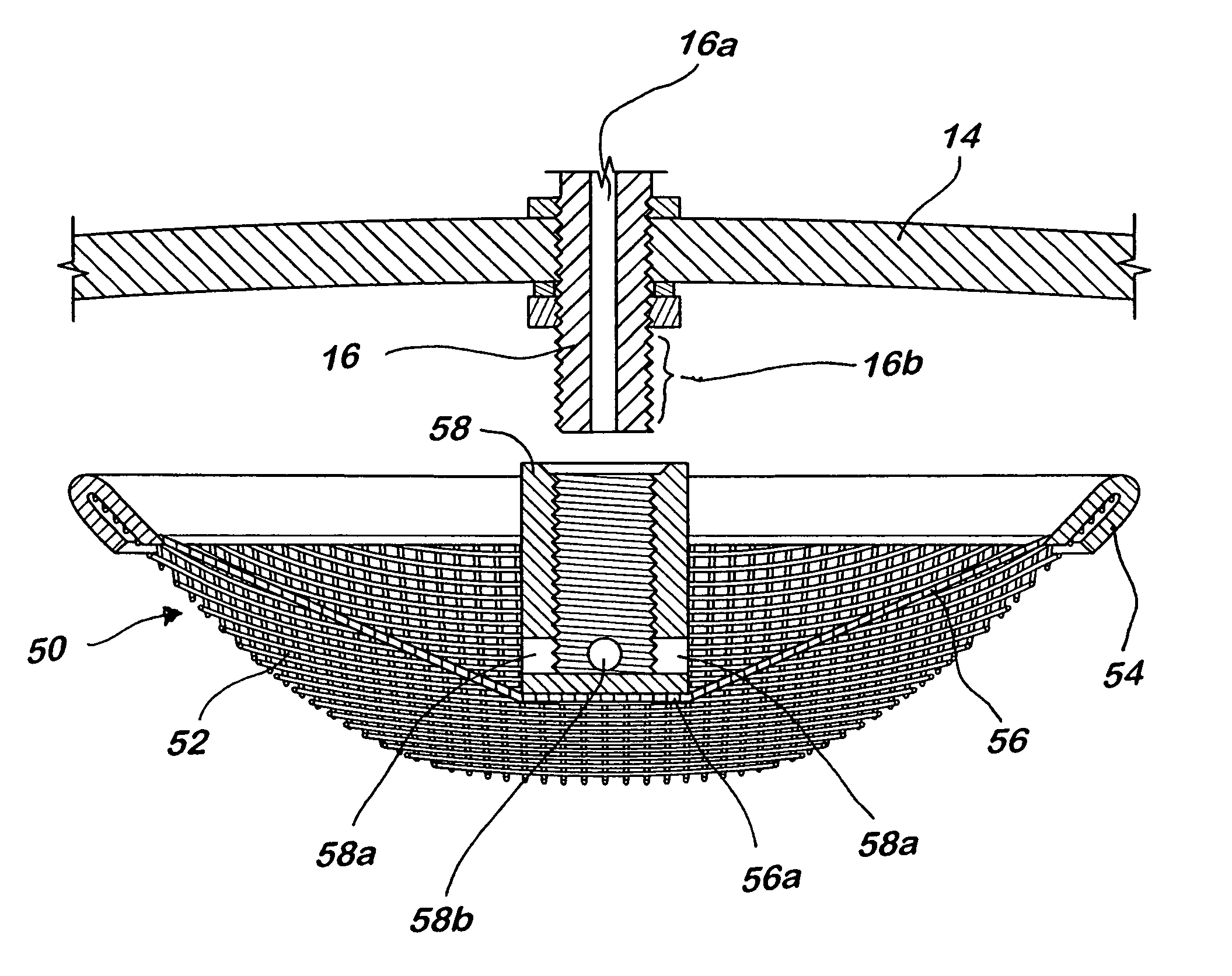
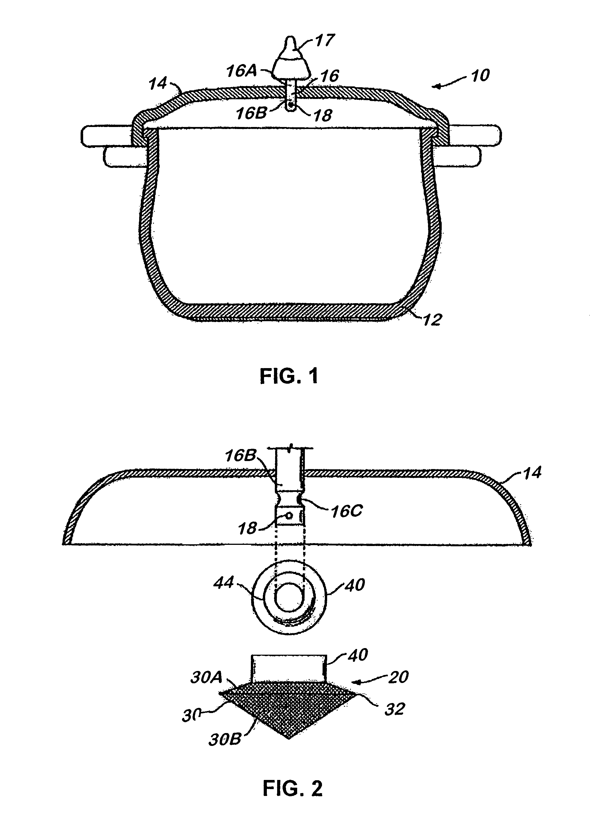
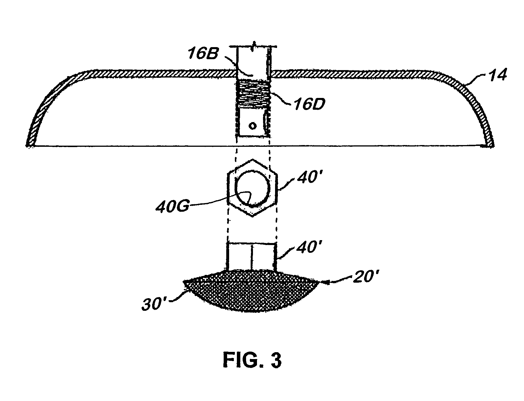
[0029]The safety cap of the present invention (See FIG. 1) is used in an ordinary pressure cooker 10 that includes a pot 12, a lid 14 and a pressure regulator or pressure release valve 16 that releases the pressure (heated or hot air) inside the pot 12 during cooking. The pressure release valve 16 is provided at the center of the lid 14 and has a pressure release passage (not shown) therein.

[0030]More specifically, the pressure release valve 16 comprises an upper portion 16A, which is exposed outside the lid 14 and has a pressure regulation weight 17, and a lower portion 16B, which is located under the lid 14 and is covered by a safety cap 20 described below. The lower portion 16B of the pressure release valve 16 is formed with air intake apertures 18 (for instance, one aperture is opened in the lower end surface of the pressure release valve 16, and four apertures are opened in the peripheral area near the lower end of the pressure release valve 16; however, only one aperture is sh...


PUM


Abstract

A protective device attached to a pressure release valve of a lid of a pressure cooker, including a dome-shaped mesh casing body, a ring-shaped reinforcing frame fixed to the upper edge of the mesh casing body, a bridge plate provided on the reinforcing frame with both ends thereof fixed to the reinforcing frame so that the bridge plate diametrically crosses the ring-shaped reinforcing frame keeping distance from the bottom of the mesh casing body, and an attachment member of substantially a hollow cylinder provided at the center of the bridge plate.

Description

BACKGROUND OF THE INVENTION[0001]1. Field of the Invention[0002]The present invention relates to a protective device or a safety cap that covers and protects the pressure release valve of a pressure cooker and to a pressure cooker installed with such a protective device.[0003]2. Prior Art[0004]A pressure cooker is a cooking utensil (pot) that utilizes high-temperature and high-pressure steam to cook food inside the pot. The pot and its lid are designed to create an airtight space inside the pot. When the pot is heated, the air inside expands. The expanding air inside the pot is unable to escape, so the atmospheric pressure within the pot increases. As the atmospheric pressure increases, the boiling point of water also increases. Thus, a pressure cooker enables the water or moisture inside the pot to become hotter than it would under the normal atmospheric pressure.[0005]With a conventional cooking pot, the water inside a pot turns into steam at around 100° C. (212° F.). The steam fr...

Claims


Application Information

Patent Timeline
Patent Type & Authority Patents(United States)
IPC IPC(8): B65D51/16
CPCA47J27/09
Inventor HASEGAWA, TOM HIROSHI
Owner HASEGAWA TOM HIROSHI
Why Eureka
Try Eureka