Display apparatus and assembling method thereof

a technology of display apparatus and assembling method, which is applied in the direction of lighting and heating apparatus, manufacturing tools, instruments, etc., can solve the problems of increasing the overall weight and volume of the liquid crystal display apparatus b>100/b, increasing the material and assembly cost of the liquid crystal display apparatus, and the manufacturing cost of the mold is very high

Active Publication Date: 2012-11-06
INNOLUX CORP
View PDF4 Cites 8 Cited by
  • Summary
  • Abstract
  • Description
  • Claims
  • Application Information

AI Technical Summary

Benefits of technology

[0008]The present invention provides an assembling method of a display apparatus, wherein the problem of over cost can be resolved.
[0023]According to the display apparatus and the assembling method thereof of the exemplary embodiments of the invention, since the number of devices is greatly reduced, the overall thickness, weight and cost of the display apparatus are correspondingly reduced. Further, the assembling process of the display apparatus is simplified.

Problems solved by technology

These components with redundant functions, not only increases the overall weight and volume of the liquid crystal display apparatus 100, it also increases the material and assembling costs of the liquid crystal display apparatus 100.
The plastic frame 136b is formed by injection molding of the plastic material and the manufacturing cost of the molds is very high.

Method used


Image

  • Display apparatus and assembling method thereof
  • Display apparatus and assembling method thereof
  • Display apparatus and assembling method thereof

Examples


Embodiment Construction

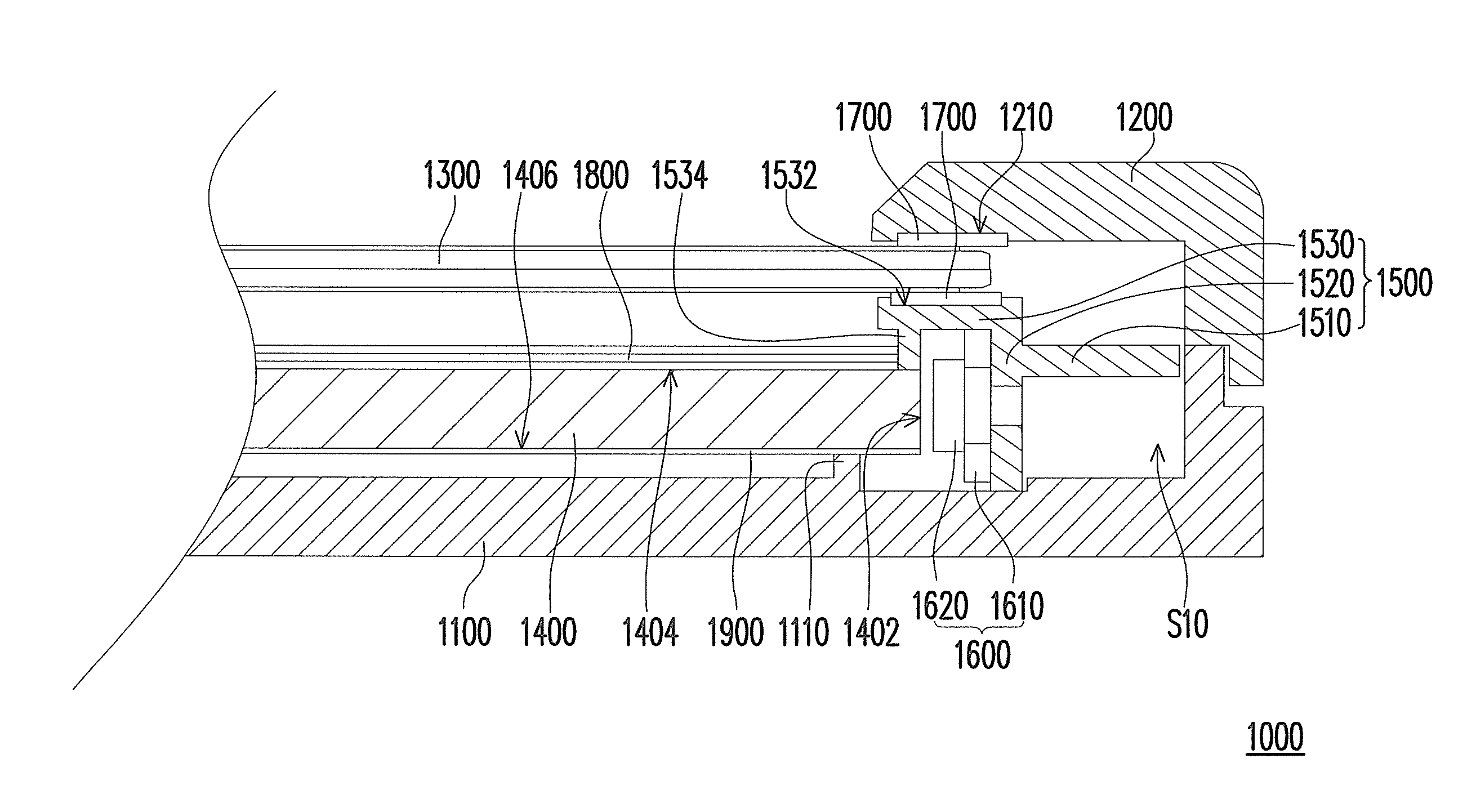
[0036]FIG. 4 is an explosive view diagram of a liquid crystal display apparatus according to an exemplary embodiment of the invention. FIG. 5 is a partial, cross-sectional view diagram of the liquid crystal display apparatus in FIG. 4. Referring to FIGS. 4 and 5, the display apparatus 1000 of this exemplary embodiment includes a back cover 1100, a front frame 1200 (this device is omitted in FIG. 4), a display panel 1300, a light guide plate 1400, at least one first metal bracket 1500 and a light emitting device 1600. The front frame 1200 is secured to the back cover 1100, and together they form an accommodating space S10. The display panel 1300 is disposed in the accommodating space S10. The light guide plate 1400 is disposed in the accommodating space S10, between the back cover 1100 and the display panel 1300. In other words, the display panel 1300 and the light guide plate 1400 are sandwiched and secured by the front frame 1200 and the back cover 1100.

[0037]The light guide plate ...


PUM

PropertyMeasurementUnit
flexibleaaaaaaaaaa
weightaaaaaaaaaa
volumeaaaaaaaaaa

Abstract

A display including a back cover, a front frame, a display panel, a light guide plate, at least one metal bracket and a light emitting element is provided. The front frame is secured to the back cover to form an accommodating space. The display panel and the light guide plate are disposed in the accommodating space. The light guide plate, which has at least one light incident surface and a light exit surface, is configured between the back cover and the display panel. The light exit surface faces toward the display panel. The metal bracket is disposed at side of the accommodating space. The metal bracket has a first part and a second part connected together. The first part is secured to at least the back cover or the front frame. The light emitting element is between the second part and the light incident surface.

Description

CROSS-REFERENCE TO RELATED APPLICATION[0001]This application claims the priority benefit of Taiwan application serial no. 99101110, filed on Jan. 15, 2010. The entirety of the above-mentioned patent application is hereby incorporated by reference herein and made a part of specification.BACKGROUND[0002]1. Field of the Invention[0003]The present invention relates to a display apparatus and an assembling method thereof, and more particularly to a light and compact display apparatus and an assembling method thereof.[0004]2. Description of Related Art[0005]With the progress in technologies, image devices have become indispensable in people's daily lives. Flat panel displays (FPD) have such superior characteristics such as light and compact, and low power consumption, that FPDs have gradually replaced conventional cathode ray tube (CRT) displays in recent years.[0006]FIG. 1 is an explosive view diagram of a conventional liquid crystal display apparatus. Referring to FIG. 1, a conventional...

Claims


Application Information

Patent Timeline
Patent Type & Authority Patents(United States)
IPC IPC(8): F21V8/00
CPCG02F1/133615Y10T29/49826
Inventor YANG, JEN-CHIHHUANG, TA-CHINKANG, CHOU-YULIN, FENG-CHANCHAO, JAW-CHIENCHU, PU-CHUN
Owner INNOLUX CORP
Why Eureka
Try Eureka