Phosphor, manufacturing method of phosphor sheet and phosphor, and light emitting device using the phosphor

a technology of phosphor and manufacturing method, which is applied in the direction of discharge tube luminescent screen, discharge tube/lamp details, luminescent composition, etc., can solve the problems of inferior color rendering properties, short life span, and color tone change, and achieve less composition shift, high emission efficiency, and less crystal strain/crystal defect

Active Publication Date: 2012-11-06
NICHIA CORP +1
View PDF22 Cites 5 Cited by
  • Summary
  • Abstract
  • Description
  • Claims
  • Application Information

AI Technical Summary

Benefits of technology

[0015]In view of the above-described problems, the present invention is provided, and an object of the present invention is to provide a new phosphor having a broad emission spectrum in a range of blue color (in a peak wavelength range from 400 nm to 500 nm), and having a broad flat excitation band in a range of the near ultraviolet / ultraviolet, and having excellent emission efficiency and emission intensity / luminance, and provide a manufacturing method of a phosphor sheet and the phosphor, and a light emission device including white LED illumination using this phosphor.Means for Solving the Problem
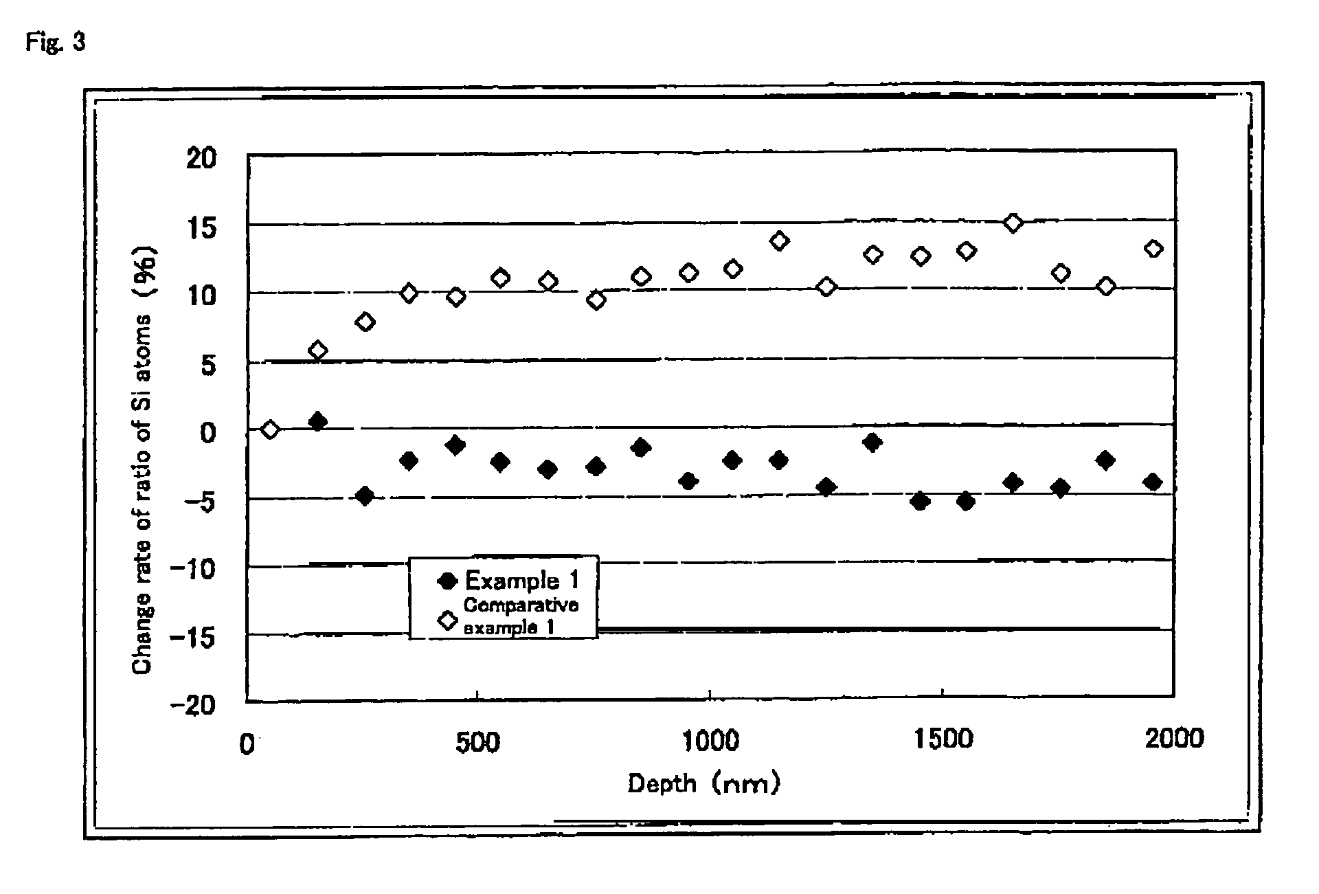
[0108]In addition, when the firing is performed with the crucible covered with a lid during firing, preferably it is possible to prevent the deviation of the distribution of atoms from the surface inside of the phosphor particle, and decrease of the emission intensity can be suppressed. This is because by covering the crucible, separation of Si atoms and oxygen atoms from the surface of the particle is suppressed, and diffusion of the Si atoms and the oxygen atoms from inside of the particle to the surface of the particle is prevented. In the phosphor thus fired, the deviation of the distribution of atoms inside of the particles is suppressed. Then, as a result of suppressing the deviation of the distribution of atoms inside of the particle, the deviation of the composition inside of the particle is also suppressed, and the phosphor with less crystal defect / crystal strain, less impurity phase, and high emission efficiency can be obtained.

Problems solved by technology

At present, a discharge type fluorescent lamp and an incandescent bulb used as the illumination device involve problems that a harmful substance such as mercury is contained, and life span is short.
Initially, although this white LED illumination has high luminance, light emission on the longer wavelength side of a visible light region, namely light emission of a red color component is insufficient, thus involving a problem of inferior color rendering properties, which is an important factor as illumination.
However, the white LED illumination, in which the high luminance blue LED and the garnet-based yellow phosphor are combined, has problems that the garnet-based yellow phosphor has no flat excitation band in the vicinity of the excitation band wavelength 460 nm, and there is a variation in emission intensity of the high luminance blue LED and the peak wavelength, and a balance of the emission intensity of blue and yellow is lost when the phosphor is applied on the LED because the emission intensity of transmitted blue light is changed depending on a film thickness, resulting in change of color tone of the white light.
Further, even when there is a variation in the emission intensity and the peak wavelength, as is seen in the high luminance blue LED, the near ultraviolet / ultraviolet ray is not utilized in mixing color of the light.
Therefore, phenomenon such as changing the color tone of the white light is not allowed to occur, and the white LED illumination with excellent color rendering properties and no variation of color tones can be manufactured.
However, there is no high efficient and high luminance R, G, B and other phosphors such as a YAG:Ce phosphor used in a combination of the high luminance blue LED and the garnet-based yellow phosphor.
Therefore, satisfactory white LED illumination can not be obtained.

Method used


Image

  • Phosphor, manufacturing method of phosphor sheet and phosphor, and light emitting device using the phosphor
  • Phosphor, manufacturing method of phosphor sheet and phosphor, and light emitting device using the phosphor
  • Phosphor, manufacturing method of phosphor sheet and phosphor, and light emitting device using the phosphor

Examples


example 1

[0115]A sample according to an example 1 was manufactured by the following procedure. SrCO3(3N), Al2O3(3N), AlN(3N), Si3N4(3N), and Eu2O3(3N) were prepared, and 0.950 mol of SrCO3, 0.25 / 3 mol of Al2O3, (0.9−0.25 / 3×2) mol of AlN, 2 mol of Si3N4, and 0.050 / 2 mol of Eu2O3 were weighed and mixed by using the mortar in the atmospheric air, so that the molar ratio of each element becomes Sr:Al:Si:Eu=0.950:0.9:6.0:0.050. The mixed raw materials were put in the BN crucible, and were set in the furnace, with an upper side of the crucible covered with the container made of BN, which was one size larger than the BN crucible, as a lid. Then, after the inside of the furnace was vacuumized and replaced with nitrogen, the temperature was increased to 1600° C. at 15° C. / min, and the raw materials were retained and fired for 3 hours at 1600° C., under the in-furnace pressure of 0.05 MPa in the circulating nitrogen atmosphere (in a flow state set at 20.0 L / min). Thereafter, the temperature was cooled...


PUM

PropertyMeasurementUnit
wavelengthaaaaaaaaaa
molar ratioaaaaaaaaaa

Abstract

To provide a phosphor given by a general composition formula expressed by MmAaBbOoNn:Z, (wherein element M is one or more kinds of elements having bivalent valency, element A is one or more kinds of elements having tervalent valency, element B is one or more kinds of elements having tetravalent valency, O is oxygen, N is nitrogen, and element Z is one or more kind of activating agent, satisfying m>0, a>0, b>0, o≧0, and n>0), with a change rate of a ratio of element B atoms to the total numbers of atoms being smaller by 10% or the change rate of oxygen atoms to the total numbers of atoms being smaller by 40% in a range from a particle surface up to depth 2000 nm, having a broad emission spectrum in a range of blue color, having a broad flat excitation band in a range of near ultraviolet / ultraviolet, and having excellent emission efficiency, emission intensity, and luminance.

Description

TECHNICAL FIELD OF THE INVENTION[0001]The present invention relates to a phosphor containing nitrogen used for a cathode-ray tube (CRT), a display such as a field emission display (FED) and a plasma display (PDP), and an illumination device such as a fluorescent lamp and a fluorescent display tube, and an illumination device such as a crystal liquid back light, a manufacturing method of a phosphor sheet and the phosphor, and also to a light emission device such as a white LED illumination device (simply called “a white LED illumination” hereafter) in which a semiconductor light emitting element (LED) and the phosphor are combined.BACKGROUND OF THE INVENTION[0002]At present, a discharge type fluorescent lamp and an incandescent bulb used as the illumination device involve problems that a harmful substance such as mercury is contained, and life span is short. However, in recent years, a high luminescence LED emitting light of near ultraviolet / ultraviolet to blue color has been develop...

Claims


Application Information

Patent Timeline
Patent Type & Authority Patents(United States)
IPC IPC(8): C09K11/64H01J29/20
CPCC09K11/7734C09K11/0883C09K11/77348C09K11/64C09K11/77H01J29/20
Inventor GOTOH, MASAHIROSAKANE, KENJI
Owner NICHIA CORP
Why Eureka
Try Eureka