Phosphor and manufacturing method of the same, and light emitting device using the phosphor

a technology of phosphor and manufacturing method, which is applied in the direction of discharge tube/lamp details, discharge tube luminescent composition, discharge tube luminescent screen, etc., can solve the problems of loss of the balance of emission intensity, short life span, and deterioration of color rendering properties, which are essential factors of illumination, etc., to achieve excellent emission efficiency and emission intensity/luminance, easy to be pulverized, and high efficiency

Inactive Publication Date: 2006-10-05
MITSUBISHI CHEM CORP
View PDF44 Cites 99 Cited by
  • Summary
  • Abstract
  • Description
  • Claims
  • Application Information

AI Technical Summary

Benefits of technology

[0011] In view of the above-described problems, the present invention is provided, and an object of the present invention is to provide a phosphor having a broad emission spectrum in a range of blue color (in a peak wavelength range from 400 nm to 500 nm), having a flat broad excitation band in the range of the near ultraviolet / ultraviolet, and having an excellent emission efficiency, emission intensity, and luminance, a method of manufacturing therefore, and a light emitting device such as white LED illumination using the phosphor.
[0040] According to the phosphor of any one of the first to fifteenth aspects, the phosphor has an excitation band with high efficiency in the range of the near ultraviolet / ultraviolet, has the emission spectrum in the range of blue color (in a peak wavelength range from 400 nm to 500 nm) when excited by the light in the range of the near ultraviolet / ultraviolet, and has excellent emission efficiency and emission intensity / luminance.
[0041] According to the phosphor of the fifteenth aspect, the phosphor thus obtained is in a powdery state, therefore is easy to be pulverized, and can be applied on various places as a paste. In addition, the average particle size (D50) of the phosphor is not less than 1.0 μm and not more than 50.0 μm, and therefore coating density can be increased, whereby a coating film having high emission intensity and luminance can be obtained.
[0042] According to the manufacturing method of the phosphor of any one of the sixteenth to twentieth aspects, the phosphor according to any one of the first to fifteenth aspects can be manufactured at a low manufacturing cost.
[0043] According to the light emitting device of any one of the twenty-first to twenty-third aspects, a high efficient light emitting device can be obtained, having a desired emission color and high emission intensity and luminance.

Problems solved by technology

At present, a discharge type fluorescent lamp and an incandescent bulb used as the illumination device involve problems that a harmful substance such as mercury is contained, and life span is short.
However, the problem of the white LED illumination is that the emission on the long-wavelength side of visible light range, specifically the emission of red color component is insufficient although the white LED illumination has a high luminance, thereby deteriorating in the color rendering properties which are essential factors of illumination.
However, problems are involved in the white LED illumination, in which the high luminance blue LED and the garnet yellow phosphor are combined, such that the garnet yellow phosphor does not have a flat broad excitation band near the excitation wavelength of 460 nm, there are variances in the emission intensity and the peak wavelength of the high luminance blue LED, and the emission intensity of transmitted blue light depending on a film thickness is changed when the phosphor is applied on the LED.
And these facts cause a lost balance of the emission intensity of blue color and yellow color, thereby changing a color tone of the white light.
However, there is no high efficient and high luminance R, G, B and other phosphor such as the YAG:Ce phosphor used in combination with the high luminance blue LED and the garnet yellow phosphor, and therefore a satisfactory white LED illumination can not be obtained.
However, although the nitrogen-containing phosphor of the aforementioned patent document 1 has the emission spectrum with a broad peak, the emission intensity under the excitation of the excitation light of near ultraviolet / ultraviolet does not meet a satisfactory level, and therefore a sufficient emission intensity and luminance can not be obtained.
Thus, the phosphor of the patent document 1 is inadequate to be used in the light emitting device.

Method used


Image

  • Phosphor and manufacturing method of the same, and light emitting device using the phosphor
  • Phosphor and manufacturing method of the same, and light emitting device using the phosphor
  • Phosphor and manufacturing method of the same, and light emitting device using the phosphor

Examples


examples 7 to 15

, and Examples 16 to 24

[0157] In the examples 7 to 24, the mixing composition and the target composition for obtaining the phosphor having high emission intensity were examined, by changing the mixing composition of Si and the amount of oxygen during weighing and mixing the raw materials.

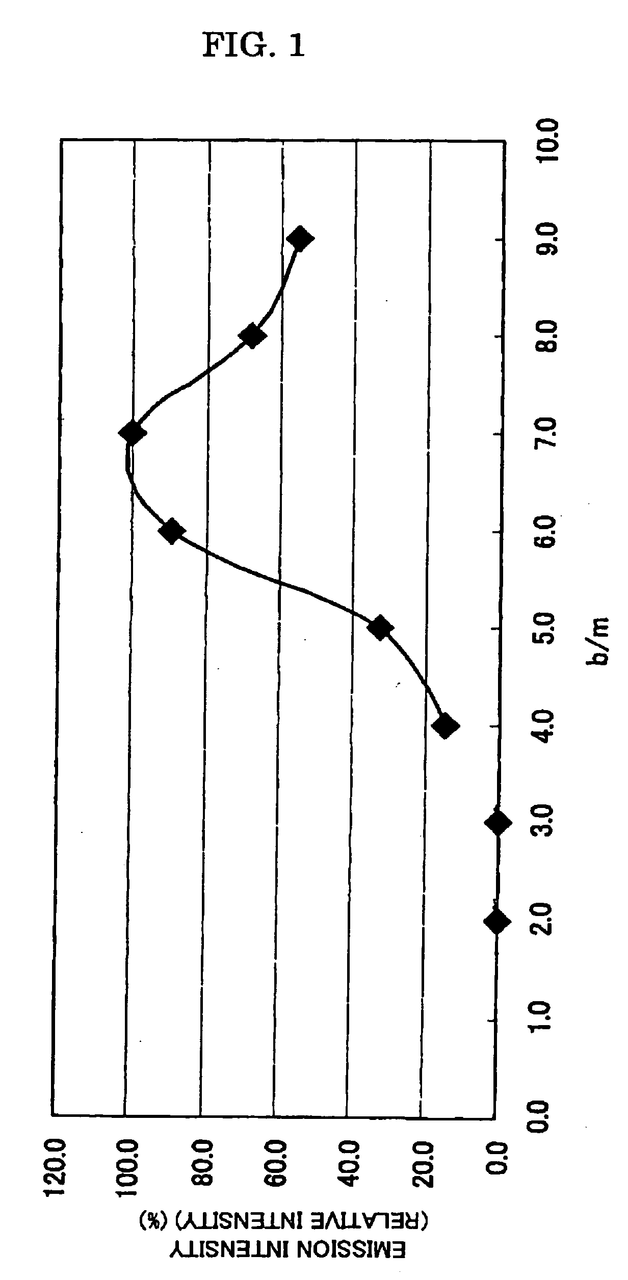
[0158] First, in the examples 7 to 15, the emission intensity was examined when the o / m ratio is changed this time, for the sample of b / m=7 (example 4) exhibiting highest emission intensity in the examples 1 to 6.

[0159] The samples of the examples 7 to 15 were manufactured by the procedure described below.

[0160] As the raw materials, the commercially available Sr3N2(2N), SrCO3(3N), Al2O3(3N), AlN(3N), Si3N4(3N), Eu2O3(3N) were prepared, and the phosphor sample was manufactured in the same way as the example 1, excepting that the molar ratio of Sr, Al, and Si was fixed to 1, 1, 7, respectively and the o / m ratio thereof was set at o / m=0 (example 7) in the phosphor expressed by a raw material mixing...

examples 25 to 30

[0170] In the examples 25 to 30, by changing the value of the a / m ratio, the mixing composition and a target composition were examined, for obtaining the phosphor having high emission intensity.

[0171] Specifically, in the phosphor expressed by the raw material mixing composition SrAlaSi6.5ONn:Eu(Eu / (Sr+Eu)=0.030, n=2 / 3m+a+4 / 3b−2 / 3o, m=1, o=1, and b=6.5), the molar ratio of Sr, Si, and O was fixed to 1, 6.5, and 1, respectively, the sample with a / m ratio set in the range from 0.5 to 2.0 was mixed and fired, and the emission intensity was measured. (b / m=6.5, o / m=1.0)

[0172] First, the samples of examples 25 to 30 were manufactured by the following procedure.

[0173] As the raw materials, the commercially available SrCO3(3N), Al2O3(3N), AlN(3N), Si3N4(3N), Eu2O3(3N) were prepared, and the phosphor sample was manufactured in the same way as the example 1, excepting that the mixing ratio of each raw material was adjusted, so that a predetermined a / m ratio of each raw material was obtaine...

examples 31 to 35

[0177] In the examples 31 to 35, the relation between the concentration of the activator element Z (Eu) and the emission intensity was examined in the phosphor manufactured in the example 20. Here, the raw material mixing ratio of Sr and Eu was adjusted so that the relation between the activator Eu and Sr became m+z=1 in the composition formula of the phosphor manufactured in the example 20, and a measured sample was manufactured.

[0178] First, the examples 31 to 35 were manufactured by the following procedure.

[0179] As the raw materials, the commercially available SrCO3(3N), AlN(3N), Si3N4(3N), Eu2O3(3N) were prepared, and the phosphor sample was manufactured in the same way as the example 20, excepting that the mixing ratio of each raw material was adjusted, and an Eu activating concentration was set to be Eu / Sr++Eu)=0.001 (example 31), Eu / (Sr+Eu)=0.005 (example 32), Eu / (Sr+Eu)=0.020 (example 33), Eu / (Sr+Eu)=0.050 (example 34), and Eu / (Sr+Eu)=0.100 (example 35).

[0180] The peak w...


PUM


Abstract

To provide a phosphor having a broad emission spectrum in a range of blue color (peak wavelength from 400 nm to 500 nm), having a broad and flat excitation band in the range of near ultraviolet / ultraviolet, and having excellent emission efficiency and emission intensity / luminance. The phosphor is expressed by a general composition formula MmAaBbOoNn:Z (where element M is more than one kind of element having bivalent valency, element A is more than one kind of element having tervalent valency, element B is more than one kind of element having tetravalent valency, O is oxygen, N is nitrogen, and element Z is more than one kind of element acting as an activator.), satisfying 5.0<(a+b) / m<9.0, 0≦a / m≦2.0, 0≦o<n, n=2 / 3m+a+4 / 3b−2 / 3o, and having an emission spectrum with a maximum peak wavelength from 400 nm to 500 nm under an excitation of the light in a wavelength range from 350 nm to 430 nm.

Description

TECHNICAL FIELD OF THE INVENTION [0001] The present invention relates to a phosphor containing nitrogen used for a cathode-ray tube (CRT), a display such as a field emission display (FED) and a plasma display (PDP), and an illumination device such as a fluorescent lamp and a fluorescent display tube, and an illumination device such as a back light for liquid-crystal display and a method of manufacturing therefore, and also to a light emitting device such as a white LED illumination in which a semiconductor light emitting element (LED) and the phosphor are combined. BACKGROUND OF THE INVENTION [0002] At present, a discharge type fluorescent lamp and an incandescent bulb used as the illumination device involve problems that a harmful substance such as mercury is contained, and life span is short. However, in recent years, a high luminescence LED emitting light of near ultraviolet / ultraviolet to blue color has been developed in sequence, and the white LED illumination for the practical...

Claims


Application Information

Patent Timeline
Patent Type & Authority Applications(United States)
IPC IPC(8): H01L33/00H01L21/00H01L33/50
CPCC09K11/0883H01L33/502C09K11/7734H01L2924/181H01L2224/48091H01L2224/48247H01L2224/48257H01L2224/8592C09K11/77347C09K11/77348H01L2924/00014H01L2924/00012
Inventor NAGATOMI, AKIRASAKANE, KENJI
Owner MITSUBISHI CHEM CORP
Why Eureka
Try Eureka