Control device for adjustable bicycle seat

a control device and bicycle seat technology, applied in the direction of rod connections, cycle equipment, machine supports, etc., can solve the problems of restricted hydraulic/pneumatic adjustment devices, and achieve the effect of easy and fast assembly and less number of parts

Inactive Publication Date: 2012-11-13
HSU JUNG YU
View PDF24 Cites 126 Cited by
  • Summary
  • Abstract
  • Description
  • Claims
  • Application Information

AI Technical Summary

Benefits of technology

[0012]The secondary object of the present invention is to provide a bicycle seat adjustable device wherein the control unit is composed of two parts and is connected to the control unit and the rod located at the outer tube or the seat tube. The action unit is located out side of the seat tube and cooperated with a cable. The device includes less number of parts and can be easily and quickly assembled.
[0013]The third object of the present invention is to provide a bicycle seat adjustable device wherein the positioning unit is connected to the outer tube or the seat tube and the cable is wrapped to the positioning unit such that the cable does not shift or loosened.

Problems solved by technology

However, the hydraulic / pneumatic adjustment devices are restricted by the position of the rod so that the rod has to be connected to the related hydraulic / pneumatic parts.

Method used


Image

  • Control device for adjustable bicycle seat
  • Control device for adjustable bicycle seat
  • Control device for adjustable bicycle seat

Examples


second embodiment

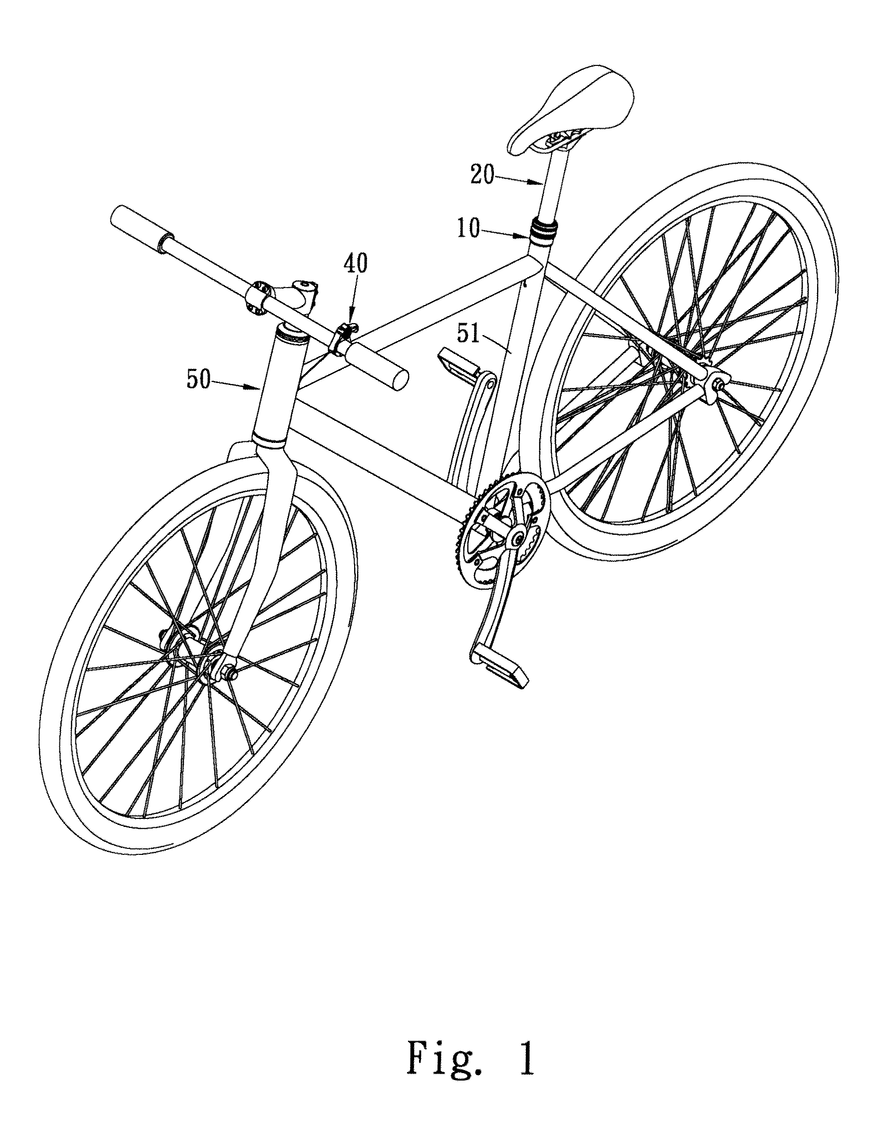
[0050]FIG. 9 shows the present invention, wherein the outer tube 10 is integrally formed with the seat tube 51 of the bicycle frame 50. The outer tube 10 has a positioning block 14 and the cable 421 extends through the positioning block 14 and is guided by the positioning block 14.

first embodiment

[0051]In this embodiment, the seat tube 51 replaces the outer tube 10 and the parts are installed in the seat tube 51, and this embodiment has the same functions as those of the

third embodiment

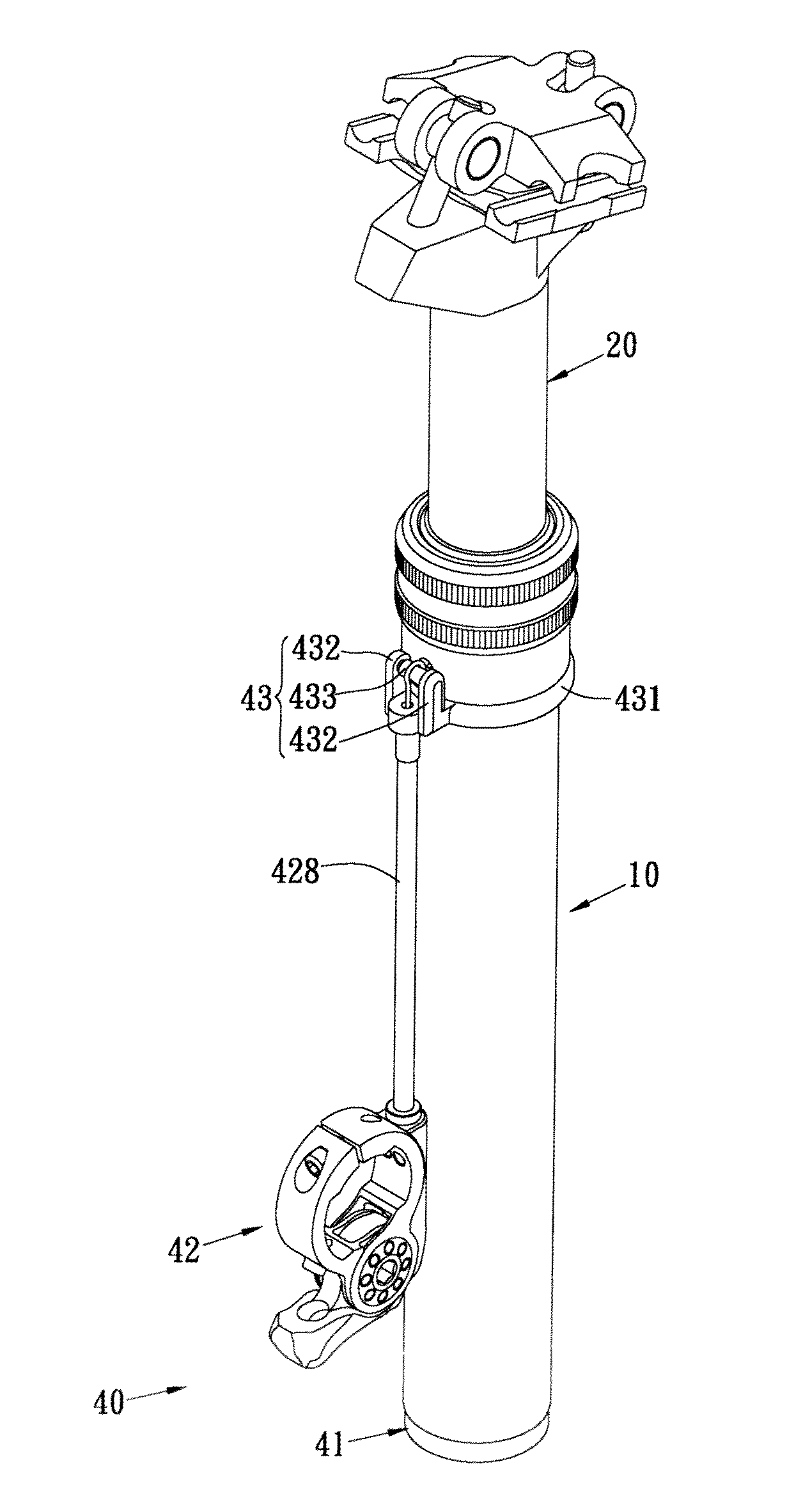
[0052]Referring to FIGS. 10 and 11, a third embodiment is disclosed, wherein the control assembly 40 has a positioning unit 43 which is mounted to the outer tube 10 and has an annular portion 431. Two base parts 432 are connected to the annular portion 431 and separated from each other at a distance. A shaft 433 is located between the two base parts 432 and the cable 421 is wrapped to the shaft 433. A sleeve 428 is mounted to the cable 421 that is exposed outside of the outer tube 10.

[0053]In this embodiment, the positioning unit 43 is provided and is connected to a pre-set position of the outer tube 10 which does not need to have extra or different shape and structure. The positioning unit 43 guides the cable 421 to wrap correctly and prevents the cable 421 from being shifted.

[0054]Besides, the shaft 433 can be a fixed rod or a rod that is pivotable and can spin so as to drive the cable 421. The sleeve 428 protects the cable 421 from the water and dust.


PUM


Abstract

A bicycle seat adjustable device includes an outer tube and an inner tube inserted into the outer tube. A piston seat and a clamp unit are connected to the inner tube. A valve unit extends through the piston seat and is located in the inner tube. The valve unit includes a rod extending through the piston seat and reaches the bottom end of the outer tube. A control unit has a control unit connected to the bottom end of the outer tube and an action unit is located outside of the outer tube. The control unit has a push member connected with the rod. The action unit has a cable extending through the outer tube and connected to the push member. A switch is connected to the cable. The push member is indirectly moved to move the rod to control the hydraulic path in the piston seat by pulling the cable.

Description

FIELD OF THE INVENTION[0001]The present invention relates to a control device, and more particularly, to a control device using hydraulic and / or pneumatic means to control the hydraulic paths of the control device to adjust the height of the bicycle seat.BACKGROUND OF THE INVENTION[0002]The proper height of the bicycle seat for the cyclist is crucial for protecting the cyclist from being injured during operation the bicycle and also for obtaining maximum efficiency of the operation of the bicycle. The adjustable bicycle seat is a trend for most of the bicycles when considering the cost of custom-made bicycle frames.[0003]The existed bicycle seat adjustable devices use an adjustable mechanism located between the seat post and the seat tube so as to control the linear movement between the seat post and the seat tube. The conventional seat adjustable devices generally include mechanical adjustable devices, hydraulic / pneumatic adjustable devices, and hybrid adjustable devices which uses...

Claims


Application Information

Patent Timeline
Patent Type & Authority Patents(United States)
IPC IPC(8): F16M11/00
CPCB62J1/08Y10T403/32467B62J2001/085
Inventor HSU, JUNG YU
Owner HSU JUNG YU
Why Eureka
Try Eureka