Wireless sensor networks

a sensor network and wireless technology, applied in the direction of electric signalling details, instruments, transportation and packaging, etc., can solve the problems of low computational ability, the most power-hungry function of the transmission of data, and the major consideration of the power consumption of the sensor

Inactive Publication Date: 2012-11-13
FUJITSU LTD
View PDF9 Cites 7 Cited by
  • Summary
  • Abstract
  • Description
  • Claims
  • Application Information

AI Technical Summary

Benefits of technology

[0023]Thus, embodiments of the invention can allow the sink to be repositioned dynamically based on current suitability of selected sink locations. The pre-selection of sink locations cuts down the complexity of the sink location problem to a few alternatives.
[0028]The sink is mobile and therefore in order to fully assess each of the candidate sink locations it can be advantageous to physically position the sink at that location and receive transmission from the sensors within range of that location. Alternatively, more complex processing can estimate suitability of each of the candidate sink locations.
[0035]In the above method the sink can preferably carry out normal sensor data reception and transmission when it is in each candidate location. This allows relocation without excessive disturbance of the data collection from the sensors. In another embodiment, the sink carries out normal sensor data reception and transmission even whilst transferring between different candidate locations.

Problems solved by technology

Commonly, the sensors are unattended devices of low computational ability and reliant on battery power; thus, power consumption of sensors is a major consideration.
Transmission of data is typically the most power-hungry function of a sensor.
However, unless a sensor has some way to replenish its power, its battery will eventually become exhausted, at which point it assumes a “dead” state.
Dead sensors reduce the coverage of the network and restrict the number of available routes for data, to the point where in the worst case, the WSN is no longer operable.
This is particularly challenging when the sensors are moving, for example as a result of being mounted on a vehicle or a human body.
A sink far from the more active part(s) of a wireless sensor network will tend to receive less data, with greater delay (latency), and incur more power expenditure by the sensors, than one placed closer to the action.
In a sparse WSN (one having relatively few sensors for the geographical area covered), some positions of the sink may not allow the sink to communicate with all parts of the WSN.
Conversely, in a dense WSN there is generally no problem for all sensors to reach the sink, but those sensors closest to the sink will tend to suffer high power drain owing to the large demands on them for relaying sensor data to the sink.
This will tend to drain the available power in a short time if the sink stays still.
Thus, it is unlikely that a fixed sink will remain optimally positioned for any length of time.
By its nature, a wireless sensor network has a constantly-changing configuration, owing to changes of state of the sensors, their movements if any, and changes in the property or properties being sensed, so the appropriate position for the sink is liable to change frequently, possibly over quite short timescales.
Unfortunately, it has been shown that the problem of sink positioning in a WSN is an “NP-complete” problem and thus difficult to solve with the very limited computing resources available in the WSN.

Method used


Image

  • Wireless sensor networks
  • Wireless sensor networks
  • Wireless sensor networks

Examples


embodiment

GENERAL EMBODIMENT

[0056]A general embodiment of the present invention will now be described with reference to FIG. 4 which shows steps of a sink positioning method in a WSN. The network allows for the sink to be independently mobile, and its position to be controllable. This may be achieved, for example by mounting a sink device on a controllably moveable support, such as a vehicle or robot, or on a runner which can be translated along one or more tracks or lines. In embodiments of the present invention, the sink 70 can thus be considered as a “mobile” sink device, which is dynamically repositioned according to the method described. The method starts with the WSN already functioning. That is, the mobile sink sends and receives data as necessary to gather information from live sensors in the WSN and forward it appropriately towards an outside entity. At the start of the relocation method, candidate sink locations are selected by the sink in step S10. This selection process may for ex...

first embodiment

[0059]A first specific embodiment of the present invention will now be described with reference to FIGS. 5 to 9 showing steps of a sink positioning method.

[0060]The first embodiment takes into account changes of the maximum transmission rate I(t) for the communication links between the sensor and the sink. Changes in I(t) occur due to movements of sensors if the sensors are mobile, and their changes of status as well as (possibly) changes in ambient conditions. They also occur due to movement of the sink.

[0061]The virtual sink positioning is assumed to be performed on a time-step basis as mentioned above.

[0062]First, it is assumed that the sink is functional. To begin with (when the system first starts operating), it may be convenient to chose an initial sink location at a central point (relative to the WSN coverage area). Alternatively, any arbitrary potential sink location could be used initially, perhaps based on user convenience or the method as essentially described below. Ther...

second embodiment

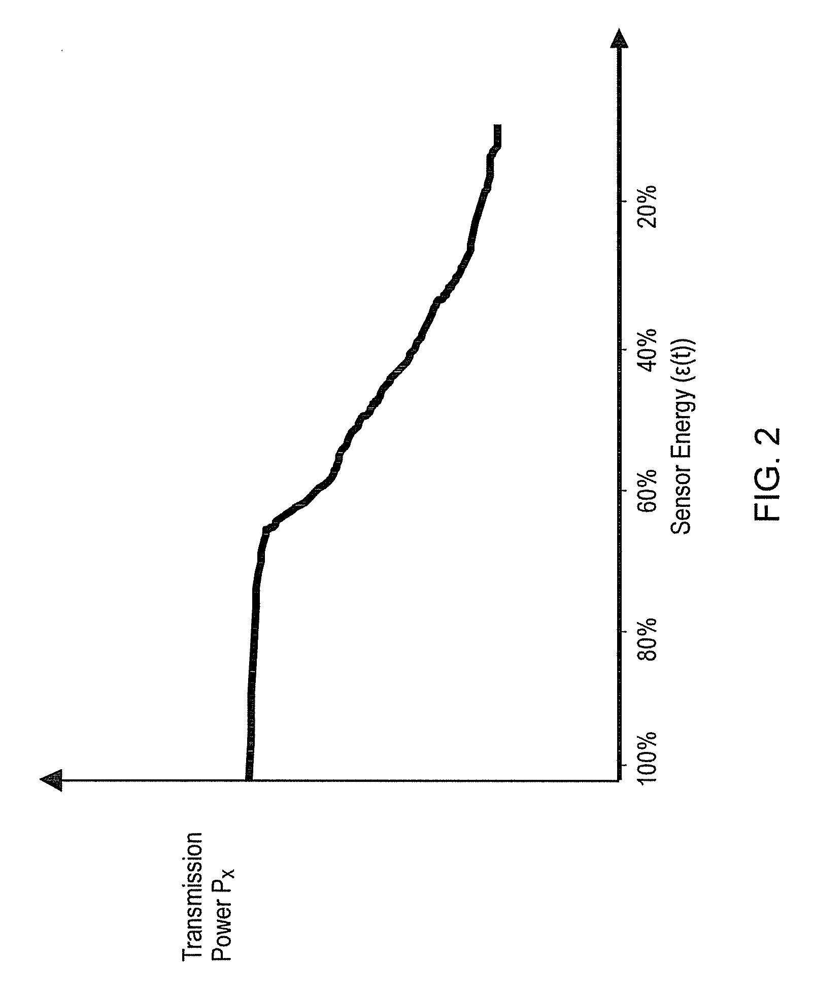
[0086]The second embodiment takes account of the needs of the sensors more completely by introducing the concept of a “desired rate” for transmission by each sensor. Each sensor's desired rate depends on its remaining energy (see FIG. 2 again) and the distance between the sensor and the sink.

[0087]As in the first embodiment it is assumed that in the current fading environment, the maximum rate I(t) for a reliable communication is random. Using Shannon's theorem, and assuming that the code length is sufficiently high, the probability that the information transmitted over channel h(t) falls below a normalised data rate R (outage probability) can be expressed as:

[0088]P⁡(I⁡(t)R)=P⁡(h⁡(t)2(2R-1)⁢N0Pa⁢d-α)(8)

where Pa is the transmission power, |h(t)|2 represents the channel capacity and the other variables are as before.

[0089]Each sensor employs a simple look-up table or equivalent which shows the distance from the sink versus the sensor energy as shown in Table 2. These two values are m...


PUM


Abstract

A wireless sensor network having mobile sensors (64, 65) is provided with a mobile sink (70). To re-position the sink, candidate sink positions are found using information from the sensors. The candidate sink locations are then assessed to give a measure of their suitability to act as the new permanent position. To do this, the sink moves to each of the candidate positions in turn and obtains data and / or signals from the sensors (64, 65) within range to estimate a total throughput expected if the sink is located at that position. The sink then transfers to the most suitable candidate position permanently, until the dynamic repositioning process is triggered again. In this way it is possible to achieve a better performance than if only the center of gravity of the sink range is taken into account to position the sink. In the second embodiment, sensors are allowed to have their say in future positioning of the sink; this involves providing a capability for the sensor that makes it possible to consider both distance from the sink and the remaining battery power to come up with the best desired maximum information rate. In effect, the sensors and sink make a collective decision on the future location of the sink.

Description

FIELD OF THE INVENTION[0001]The present invention relates to wireless sensor networks and more particularly to sink (base station) positioning in such networks.BACKGROUND OF THE INVENTION[0002]Recently, the concept of the wireless sensor network (WSN) has received considerable attention. A WSN typically includes a collection of low-power transceivers (henceforth called sensors) each having some kind of sensor function for one or more properties of an environment in which they are placed. The term “environment” here has a very broad meaning and could include, for example:—a geographical area such as a farmer's field, an area of ground requiring monitoring for security reasons, or a volcano; a specific facility such as an industrial plant, a hospital, a retail store or financial institution; or a human body. Likewise, the range of properties which might be sensed is wide, including temperature, pressure, sound, vibration, motion, the presence of specific chemicals, etc.[0003]Each sens...

Claims


Application Information

Patent Timeline
Patent Type & Authority Patents(United States)
IPC IPC(8): G08B1/08G08B21/00G06Q10/00
CPCG06Q10/04H04W4/02H04W16/18H04W4/029
Inventor ABEDI, SAIED
Owner FUJITSU LTD
Why Eureka
Try Eureka