
United AFEC and method thereof, and TDD radio repeater apparatus using the same

a radio repeater and united technology, applied in the field of united adaptive forward error correction (uafec), can solve the problems of inefficient double use of afecs having the same structure, deterioration of increase in the size of tdd radio repeaters, so as to improve the stability of the signal relay, improve the service quality, and improve the flexibility of the arrangement of each constituent elemen

Inactive Publication Date: 2012-11-13
FUJITSUU SHISUTEMU KONSUTORAKUSHIYON KK
View PDF17 Cites 2 Cited by
  • Summary
  • Abstract
  • Description
  • Claims
  • Application Information

AI Technical Summary

Benefits of technology

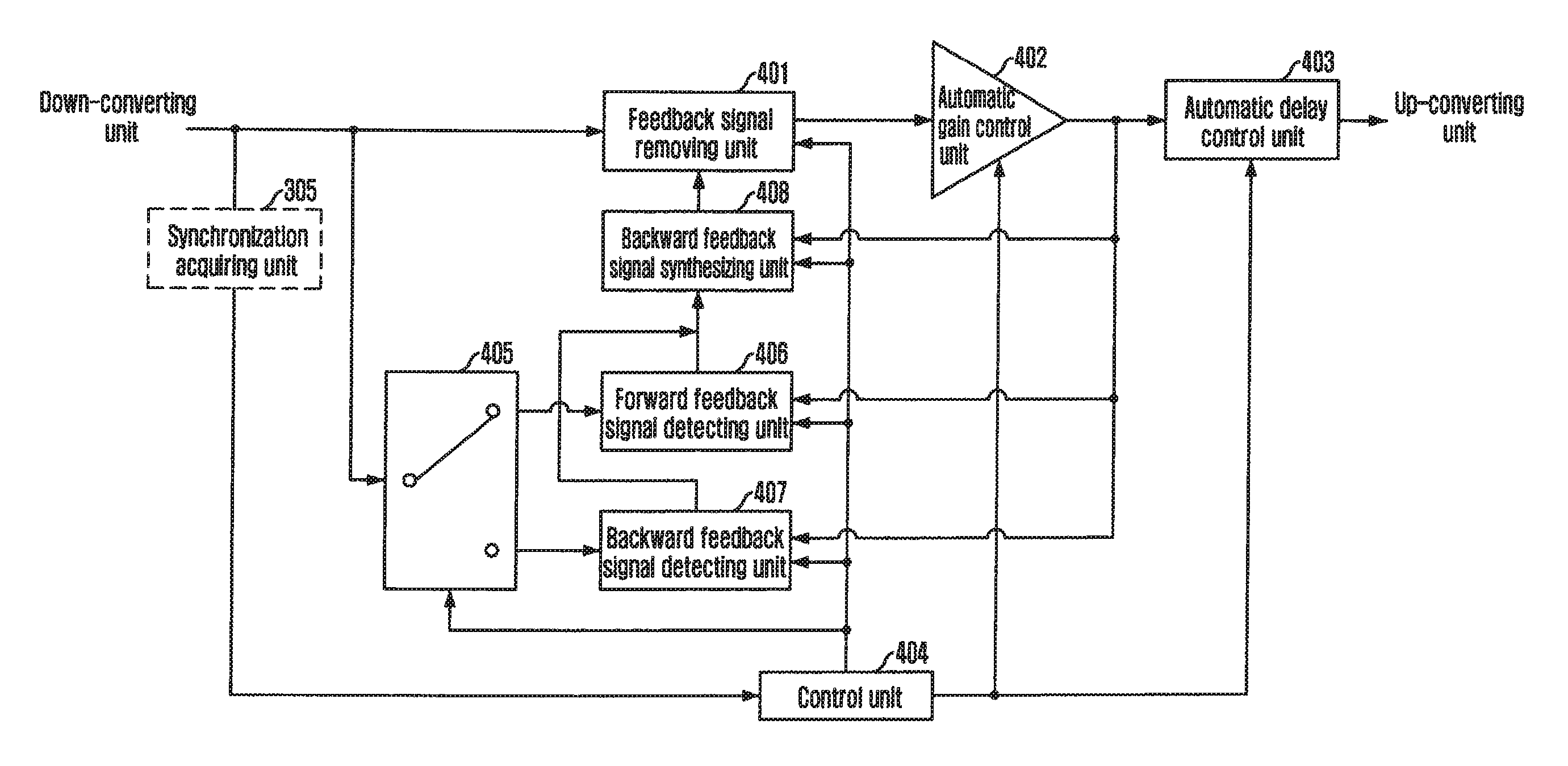
"The present invention provides a united Adaptive Forward Error Correction (U-AFEC) for improving service quality by sharing one Adaptive Forward / Backward Error Correction (AFEC) in forward / backward directions and removing feedback signals from the forward / backward relay signals. The U-AFEC method includes switching the forward and backward relay signals in accordance with control of synchronization information and detecting and updating the phase and size of the feedback signals from the gain-controlled and fed-back forward and backward relay signals. The U-AFEC system also includes an automatic delay control unit for preventing interactive interference between the feedback signal and a multipath signal. The present invention also provides a computer-readable recording medium for storing the program for realizing the method and a TDD radio repeater for improving service quality."

Problems solved by technology

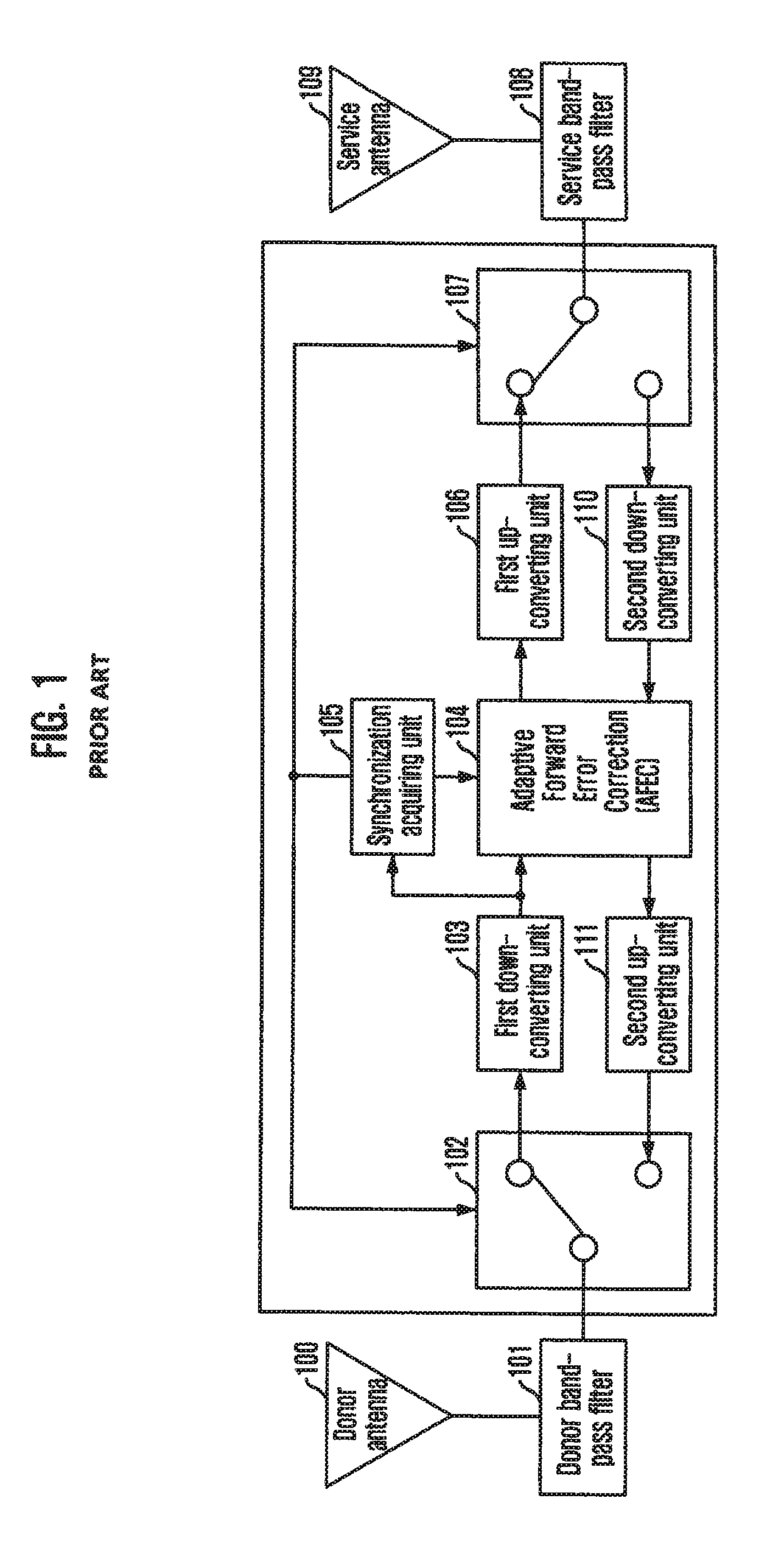
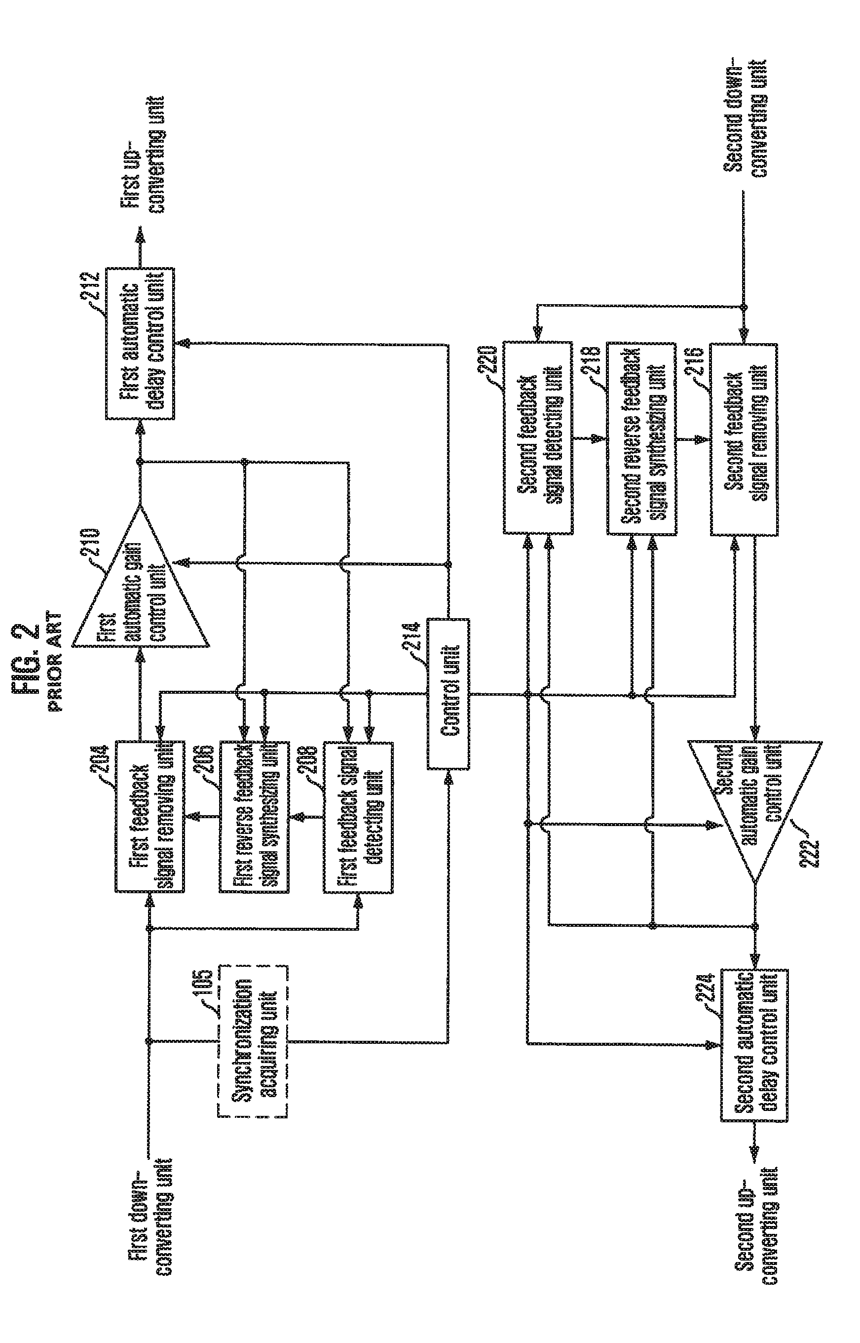
Accordingly, there are problems that flexibility in arrangement of each constituent element is deteriorated and the size of the TDD radio repeater increases.
In addition, consumption power, power loss and production cost increase and the AFECs having the same structure are inefficiently doubly used.

Method used


Image

  • United AFEC and method thereof, and TDD radio repeater apparatus using the same
  • United AFEC and method thereof, and TDD radio repeater apparatus using the same
  • United AFEC and method thereof, and TDD radio repeater apparatus using the same

Examples


Embodiment Construction

[0046]The advantages, features and aspects of the invention will become apparent from the following description of the embodiments with reference to the accompanying drawings, which is set forth hereinafter. Therefore, those skilled in the field of this art of the present invention can embody the technological concept and scope of the invention easily. In addition, if it is considered that detailed description on a related art may obscure the points of the present invention, the detailed description will not be provided herein. The preferred embodiments of the present invention will be described in detail hereinafter with reference to the attached drawings.

[0047]FIG. 3 is a block diagram showing a Time Division Duplex (TDD) radio repeater in accordance with an embodiment of the present invention.

[0048]As shown in FIG. 3, the TDD radio repeater in accordance with the present invention includes a donor antenna 300, a service antenna 311, a donor band-pass filter 301, a donor switching...


PUM


Abstract

Provided is a united Adaptive Forward Error Correction (U-AFEC), including: an automatic gain control unit for controlling a gain of forward / backward relay signals; a switching unit for switching the forward / backward relay signals; a forward feedback signal detecting unit for detecting and updating a phase and a size of a feedback signal; a backward feedback signal detecting unit for detecting and updating the phase and the size of the feedback signal; a reverse feedback signal synthesizing unit for generating a reverse feedback signal based on the phase and the size of the feedback signal; a feedback signal removing unit for removing the feedback signal in the forward / backward relay signals and transmitting the forward / backward relay signals to the automatic gain control unit; and a control unit for removing the feedback signal in the forward / backward relay signals and controlling each constituent element.

Description

CROSS REFERENCE TO RELATED APPLICATIONS[0001]This application is a 35 U.S.C. §371 National Phase Entry Application from PCT / KR2007 / 005949, filed Nov. 23, 2007, and designating the United States, which claims priority under 35 U.S.C. §119 to Korean Patent Application No. 10-2007-0074617 filed Jul. 25, 2007, which is incorporated herein in its entirety.TECHNICAL FIELD[0002]The present invention relates to a united Adaptive Forward Error Correction (U-AFEC) and a method thereof, a Time Division Duplex (TDD) radio repeater using the same, and a computer-readable recording medium for storing a program for realizing the method; and, more particularly, to a U-AFEC for improving a service quality by sharing one AFEC in forward / backward directions in a TDD radio repeater and completely removing a feedback signal component from a signal to be relayed and improving stability of signal relay through operation adaptive to radio channel environment change, a method thereof, a TDD radio repeater u...

Claims


Application Information

Patent Timeline
Patent Type & Authority Patents(United States)
IPC IPC(8): H04B7/14
CPCH04B1/54H04B7/15535H04B7/15585H04B7/14H04J3/00
Inventor AHN, BYUNG-YANG
Owner FUJITSUU SHISUTEMU KONSUTORAKUSHIYON KK
Learn More