
Deployable fairing and method for reducing aerodynamic drag on a gun-launched artillery shell

a technology of artillery shell and aerodynamic drag reduction, which is applied in the field of artillery shells, can solve the problems of limiting the maximum range of the shell, increasing the drag, and low pressure behind the shell, so as to reduce the area behind the shell, reduce the aerodynamic drag, and extend the range of the artillery shell

Active Publication Date: 2012-11-20
RAYTHEON CO +1
View PDF25 Cites 11 Cited by
  • Summary
  • Abstract
  • Description
  • Claims
  • Application Information

AI Technical Summary

Benefits of technology

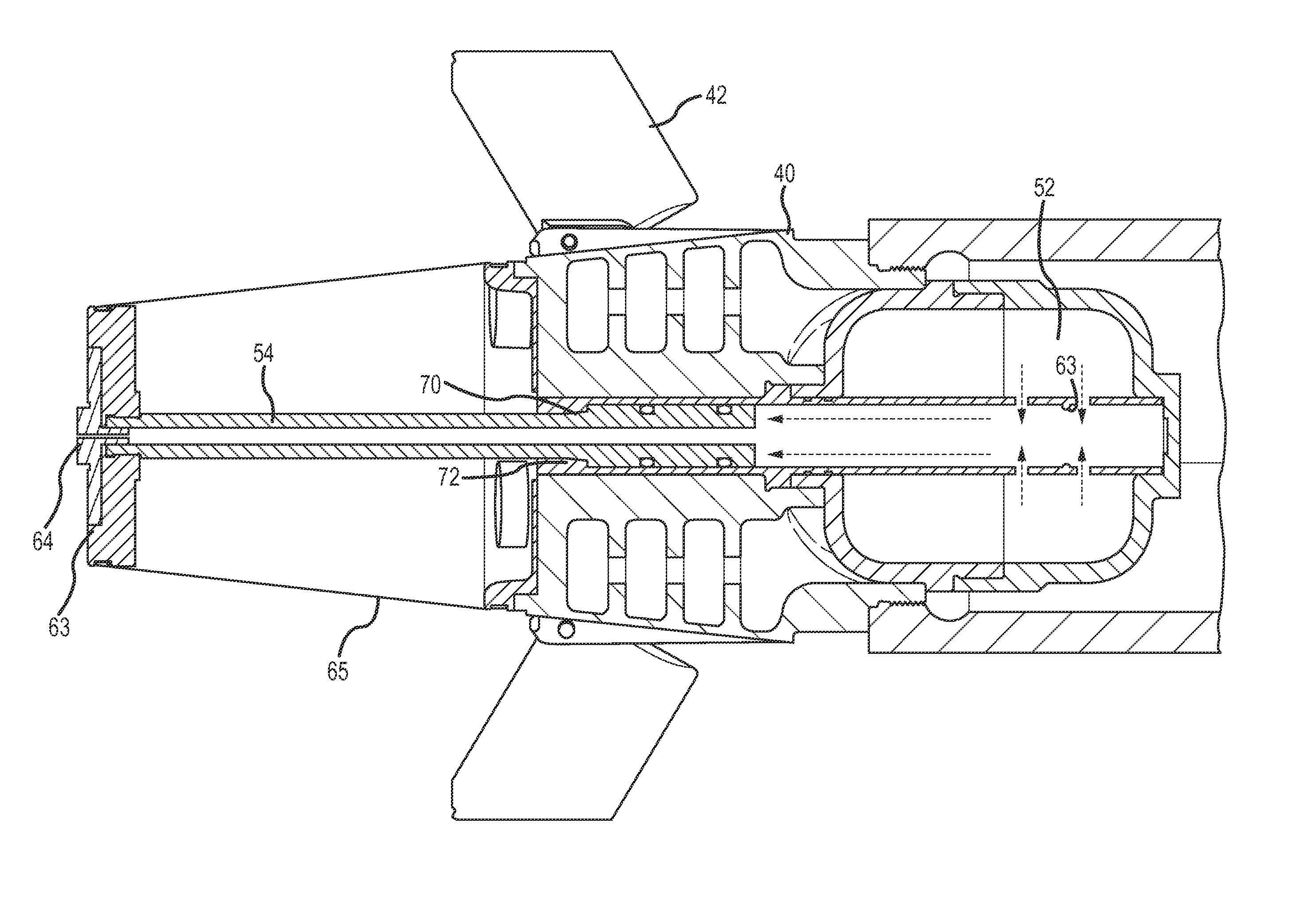
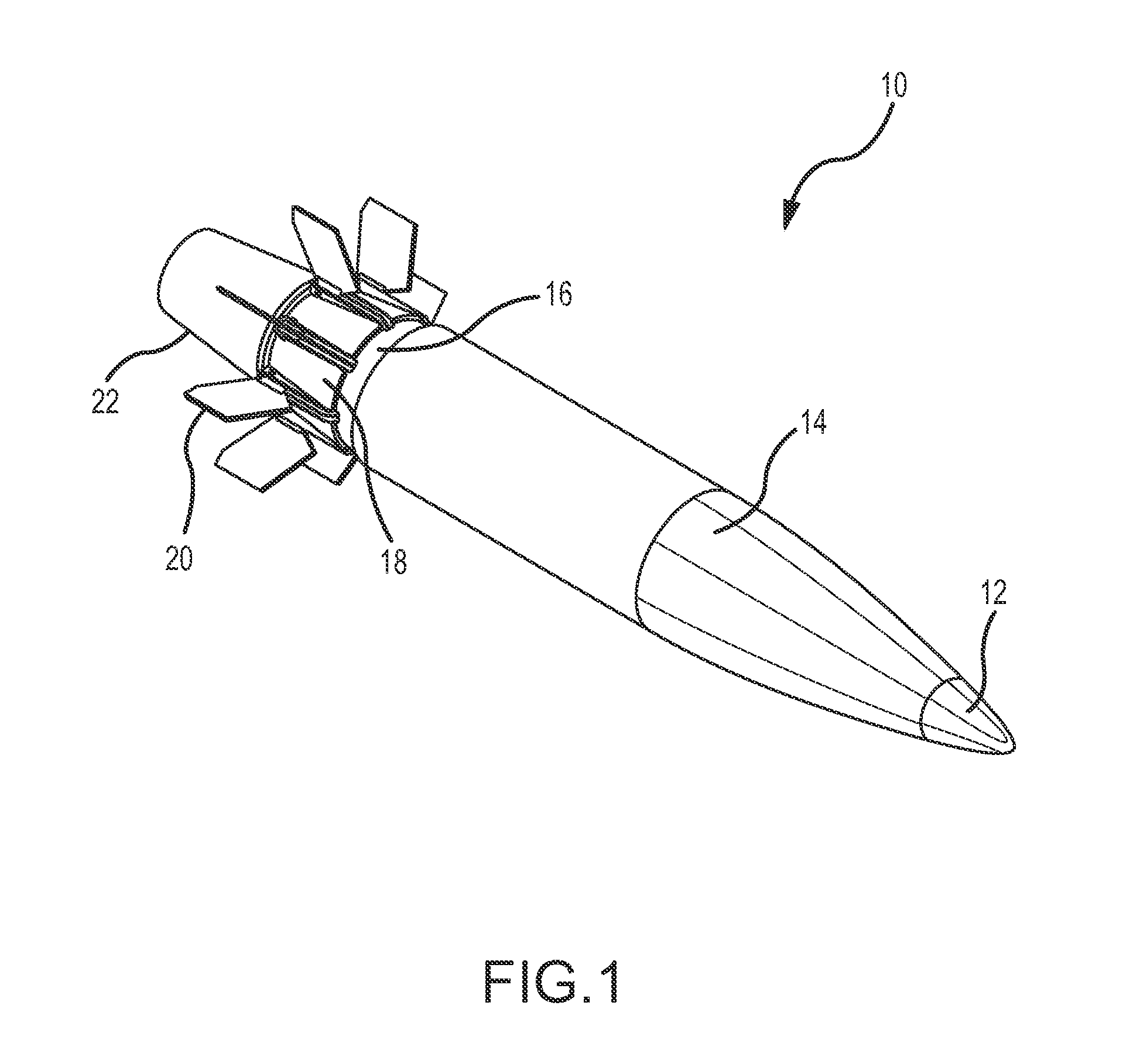
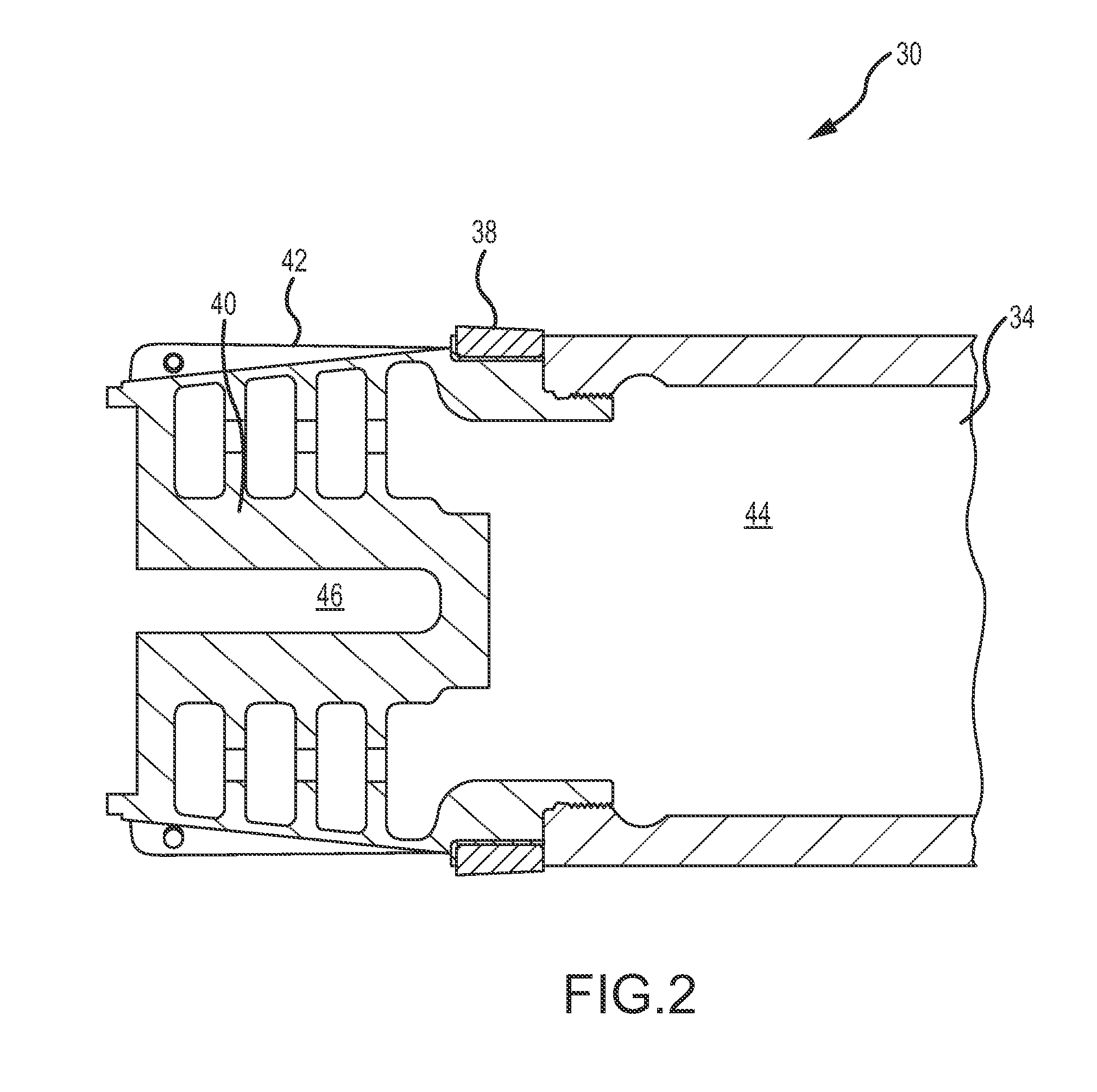
The present invention provides an improved design for a gun-launched artillery shell that reduces aerodynamic drag and extends the range of the artillery shell. This is achieved by using a fabric fairing and a piston driven off of high-pressure gun gases to deploy the fairing and reduce the area behind the shell. The high-pressure gas acts on the top surface of the piston to drive it aft and lock it in a deployed position. The invention also includes a gas intake path and a cylinder that guides the piston and extends into the chamber of the shell. The technical effects of the invention include reducing aerodynamic drag, extending range, and improving the efficiency of the artillery shell.

Problems solved by technology

It is well known that a rear surface that does not taper, or tapers too quickly, will cause the airflow to separate from the projectile at that location resulting in low pressure behind the shell.
The low-pressure region acts like a partial vacuum over the entire aft area of the shell, which increases drag thus limiting the maximum range of the shell.

Method used


Image

  • Deployable fairing and method for reducing aerodynamic drag on a gun-launched artillery shell
  • Deployable fairing and method for reducing aerodynamic drag on a gun-launched artillery shell
  • Deployable fairing and method for reducing aerodynamic drag on a gun-launched artillery shell

Examples


Embodiment Construction

[0027]The present invention describes a deployable fairing driven off of high-pressure gun gases to reduce base drag and extend the range of the artillery shell. Base drag reduction is accomplished without the use of active propellants, either to deploy the fairing or in a base-bleed configuration.

[0028]The present invention is generally applicable to all types of artillery shells for use in all types of guns that launch artillery shells from a launch tube. Artillery shells are distinguished from rockets and missiles in that artillery shells are not self-propelled, they rely on high-pressure gun gasses created in the launch tube from the deflagration of propellant within the tube to propel the shell towards a target. The “gun” may be any configuration of a launch tube and propellant (e.g. black powder, nitroglycerine, nitrocellulose, nitroguanidine or combinations thereof) configured to generate the high-pressure gun gasses to launch the shell towards the target. Such “guns” may als...


PUM


Abstract

A deployable fairing is driven off of high-pressure gun gases to reduce aerodynamic drag and extend the range of the artillery shell. An artillery shell is provided with a fabric fairing and a piston attached thereto in a rear section of the shell in a stowed state and a chamber. During launch high-pressure gun gasses are captured and stored in the chamber. Once the shell clears the end of the artillery tube, the pressure aft of the shell drops from the high pressure inside the tube to atmospheric pressure outside the tube. The high pressure gun gasses stored in the chamber act over the top surface of the piston to drive the piston aft against the much lower pressure behind the projectile to deploy the fabric fairing attached thereto to reduce the base area of the projectile creating or extending the boat-tail of the shell, hence reduce aerodynamic drag. The aft driven piston engages a locking mechanism that locks the piston in a deployed position.

Description

CROSS-REFERENCE TO RELATED APPLICATION[0001]This application claims benefit of priority under 35 U.S.C. 119(e) to U.S. Provisional Application No. 61 / 230,527, entitled “Deployable Boat-Tail Device for Use on Projectiles,” filed on Jul. 31, 2009, the entire contents of which are incorporated by reference.BACKGROUND OF THE INVENTION[0002]1. Field of the Invention[0003]This invention relates to artillery shells and more particularly to an apparatus and method for reducing drag on a gun-launched artillery shell.[0004]2. Description of the Related Art[0005]For reasons concerning firing technology, artillery shells have a rear surface at right angles to the shell axis. It is well known that a rear surface that does not taper, or tapers too quickly, will cause the airflow to separate from the projectile at that location resulting in low pressure behind the shell. The low-pressure region acts like a partial vacuum over the entire aft area of the shell, which increases drag thus limiting the...

Claims


Application Information

Patent Timeline
Patent Type & Authority Patents(United States)
IPC IPC(8): F42B10/44
CPCF42B10/44
Inventor MCDERMOTT, BRIAN K.GREENWOOD, KEVIN R.STREETER, JAMES D.
Owner RAYTHEON CO
Learn More