Communication apparatus

a communication apparatus and communication technology, applied in the field of communication apparatuses, can solve problems such as the inability to perform high-rate communication

Active Publication Date: 2012-11-20
PANASONIC SEMICON SOLUTIONS CO LTD
View PDF12 Cites 0 Cited by
  • Summary
  • Abstract
  • Description
  • Claims
  • Application Information

AI Technical Summary

Benefits of technology

[0010]The main object of the present invention therefore is to achieve a data communication at high-rate when data communication is carried out through a solid-wire communication line.
[0012]In the present invention comprising the above-described configuration, it is unnecessary to set the data communication unit time when the receiver receives the data, and the pulse interval that is converted with the reference pulse number based on the first reference value becomes the data communication unit time. Thus, when the pulse interval set in this manner is smaller than the first reference value, the data communication unit time becomes short, thereby communication from the interrogator to the receiver can be carried out at a higher rate.
[0014]According to this, it is unnecessary at the time of transmitting the data signal from the transmitter to set the data communication unit time, and the pulse interval according to the first reference value becomes the data communication unit time. Thus, when the pulse interval is smaller than the first reference value, the data communication unit time becomes short, thereby communication from the interrogator to the receiver can be carried out at a higher rate.
[0022]According to this the receiver is able to receive the data signal containing a plural kinds of data in one pulse, thereby achieving communication from the transmitter to the receiver at a high-speed.
[0024]With this, the first reference value can be set for each transmitter. Therefore, it is possible to set the first reference value and the data communication unit time in a short time regardless of production dispersion of the transmitters, and communication between the transmitter and the receiver can be performed at a high-speed. Furthermore, the first reference value can be changed optionally, so that the data analysis becomes difficult even if there is a leak of the data communicated between the transmitter and the receiver.
[0027]With this, analysis of the data can be made difficult when there is a leak of communication data exchanged between the transmitter and the receiver, since the first reference value is set in one pulse for every data communication. Furthermore, the data communication to set the first reference value can be performed at a high rate.

Problems solved by technology

Thus, it is not possible to perform high-rate communication in this case.

Method used


Image

  • Communication apparatus
  • Communication apparatus
  • Communication apparatus

Examples


first embodiment

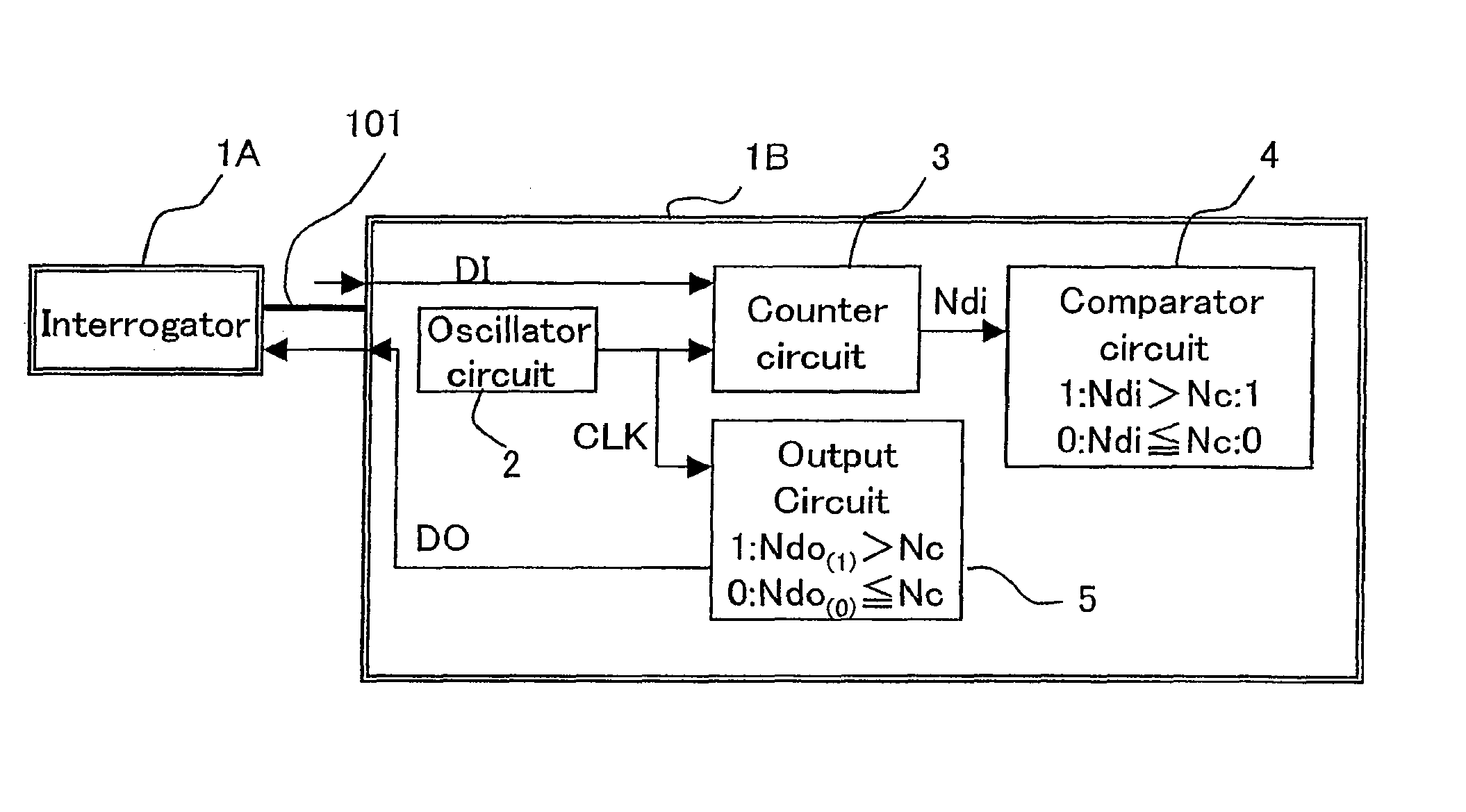
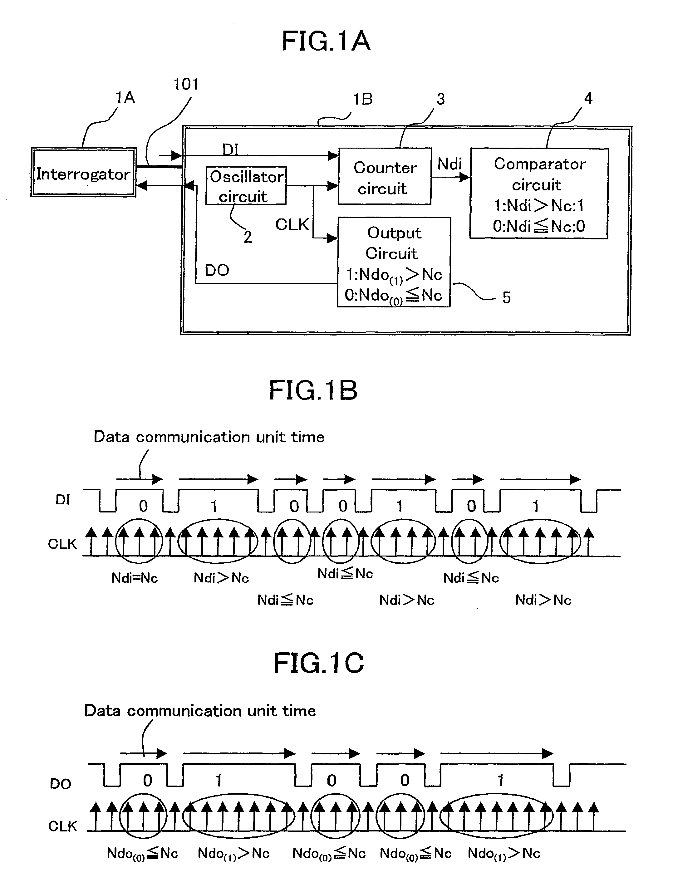
[0047]FIG. 1A is a diagram for showing the structure of a communication apparatus according to a first embodiment of the present invention. The communication apparatus comprises an interrogator 1A and a responder 1B. The interrogator 1A and the responder 1B are connected through a single communication line 101. The responder 1B comprises an oscillator circuit 2, a counter circuit 3, a comparator circuit 4, and an output circuit 5.

[0048]The oscillator circuit 2 generates reference pulse CLK. The counter circuit 3 counts pulse number Ndi of the reference pulse CLK. The pulse number Ndi counted by the counter circuit 3 is the following here. Namely, the pulse number Ndi corresponds to the pulse number of the reference pulse CLK that is outputted from the oscillator circuit 2 between a period (pulse interval) of two adjacent pulses among each of the pulses contained in the data signal DI received by the responder 1B. Therefore, the pulse number Ndi indicates the pulse interval.

[0049]A f...

second embodiment

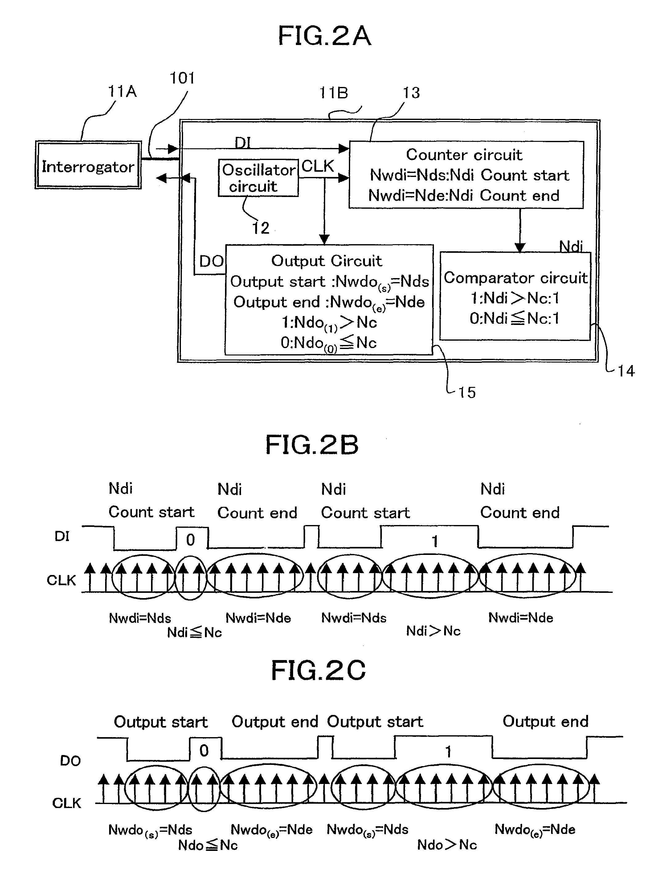
[0056]FIG. 2A is a diagram for showing the structure of a communication apparatus according to a second embodiment of the present invention. The communication apparatus comprises an interrogator 11A and a responder 11B. The interrogator 11A and the responder 11B are connected through a single communication line 101. The responder 11B comprises an oscillator circuit 12, a counter circuit 13, a comparator circuit 14, and an output circuit 15.

[0057]The oscillator circuit 12 generates reference pulse CLK. The counter circuit 13 counts the pulse number Ndi of the reference pulse CLK. The counter circuit 13 further counts the pulse number Nwdi of the reference pulse to make the reference points (count start point and count end point) for counting the pulse number Ndi. The pulse number Ndi is the same as that described in the first embodiment. In the meantime, the pulse number Nwdi corresponds to the pulse number of the reference pulse CLK that is outputted from the oscillator circuit 12 d...

third embodiment

[0068]FIG. 3A is a diagram for showing the structure of a communication apparatus according to a third embodiment of the present invention. The communication apparatus comprises an interrogator 21A and a responder 21B. The interrogator 21A and the responder 21B are connected through a single communication line 101. The responder 21B comprises an oscillator circuit 22, a counter circuit 23, and a comparator circuit 24. The oscillator circuit 22 generates reference pulse CLK. The counter circuit 23 counts the pulse number Ndi of the reference pulse CLK. The pulse number Ndi is the same as those described in the first and second embodiments. The comparator circuit 24 stores reference value Nc1 and Nc2 as the first reference values for identifying the data signal DI, and compares the stored reference values Nc1 and Nc2 with the pulse number Ndi inputted from the counter circuit 23. The reference value Nc1 is a threshold value for distinguishing the data “0” and data “1”, and the referen...


PUM


Abstract

A communication apparatus according to the present invention comprises a transmitter for generating and transmitting a data signal where data is superposed as time length of a pulse interval, and a receiver for receiving the data signal. The transmitter and the receiver are connected through a single communication line. The receiver comprises: a receiver-side oscillator circuit for oscillating a reference pulse as a count reference of the data signal; a counter circuit for counting a pulse interval of the received data signal by converting it to a reference pulse number of the oscillator circuit; and a comparator circuit stores a first reference value therein, and judges data of the data signal by comparing the pulse interval of the data signal counted by the counter circuit with the first reference value.

Description

BACKGROUND OF THE INVENTION[0001]1. Field of the Invention[0002]The present invention relates to a communication apparatus that performs communication through a solid-wire communication line.[0003]2. Description of the Related Art[0004]There is a conventional communication apparatus in which data communication is performed through a solid-wire communication line. As a method for judging 0 / 1 of data at the time of data communication between an interrogator and a responder, such communication apparatus sets a reference time by a delay circuit to judge a voltage change of a signal faster than the reference time as “0”, and a voltage change of a signal slower than the reference time as “1”, within unit time of data communication. The structure of the conventional communication apparatus will be described hereinafter by referring to the accompanying drawings.[0005]FIG. 6A is a diagram to show the construction of the related art. An interrogator 100A and a responder 100B are connected thr...

Claims


Application Information

Patent Timeline
Patent Type & Authority Patents(United States)
IPC IPC(8): H04B1/38H04L25/49
CPCH04L25/4902H04L25/4917
Inventor WADA, HIROFUMIKII, NAOTO
Owner PANASONIC SEMICON SOLUTIONS CO LTD
Why Eureka
Try Eureka