
Supporting device and dual display unit having the same

a support device and dual display technology, applied in curtain suspension devices, electric apparatus casings/cabinets/drawers, instruments, etc., can solve the problems of inability to add an auxiliary display unit to the existing display unit, the position and pose of the auxiliary display unit are very limited, and the conventional dual display uni

Active Publication Date: 2012-11-27
SAMSUNG ELECTRONICS CO LTD
View PDF21 Cites 24 Cited by
  • Summary
  • Abstract
  • Description
  • Claims
  • Application Information

AI Technical Summary

Benefits of technology

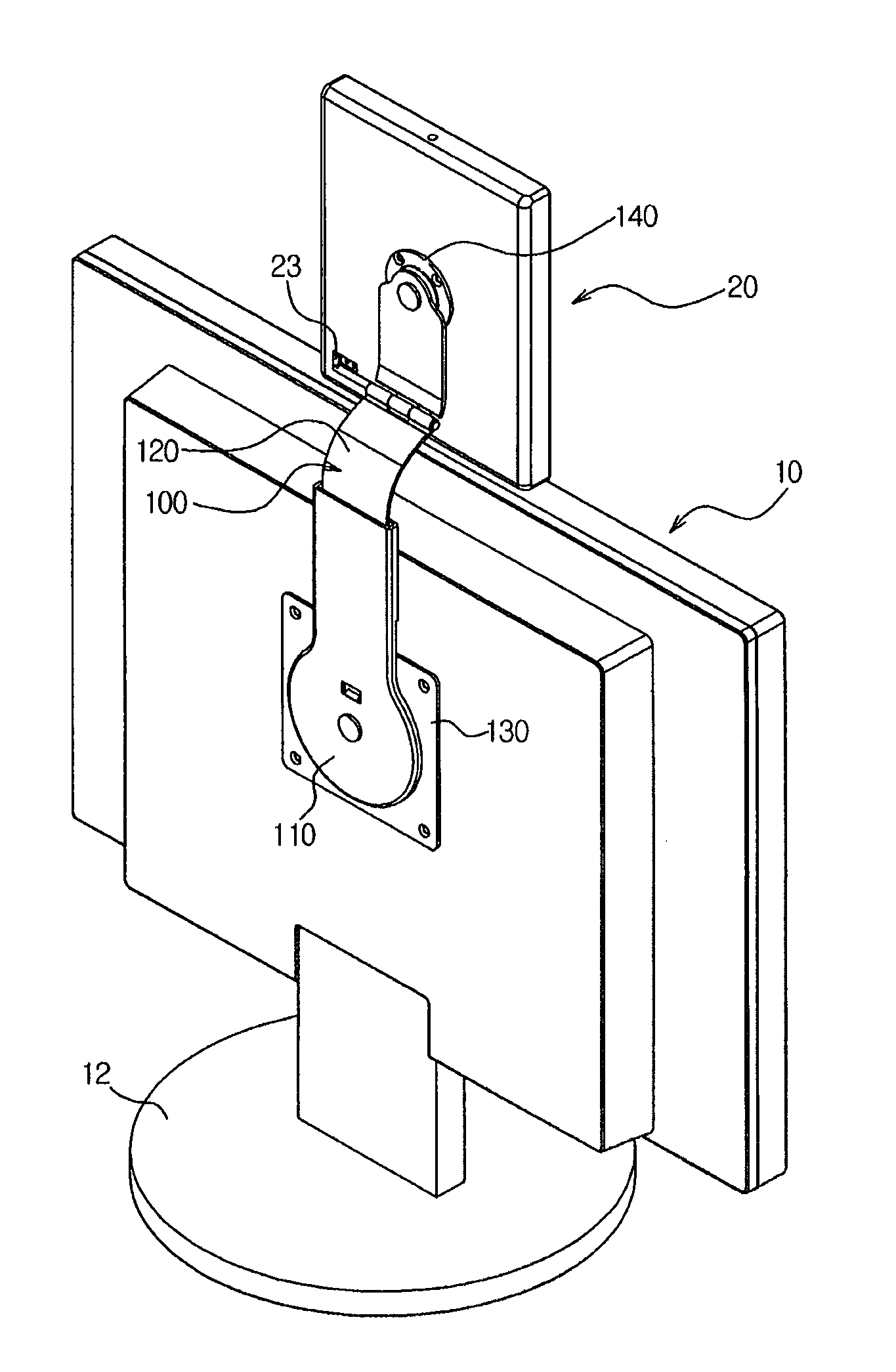
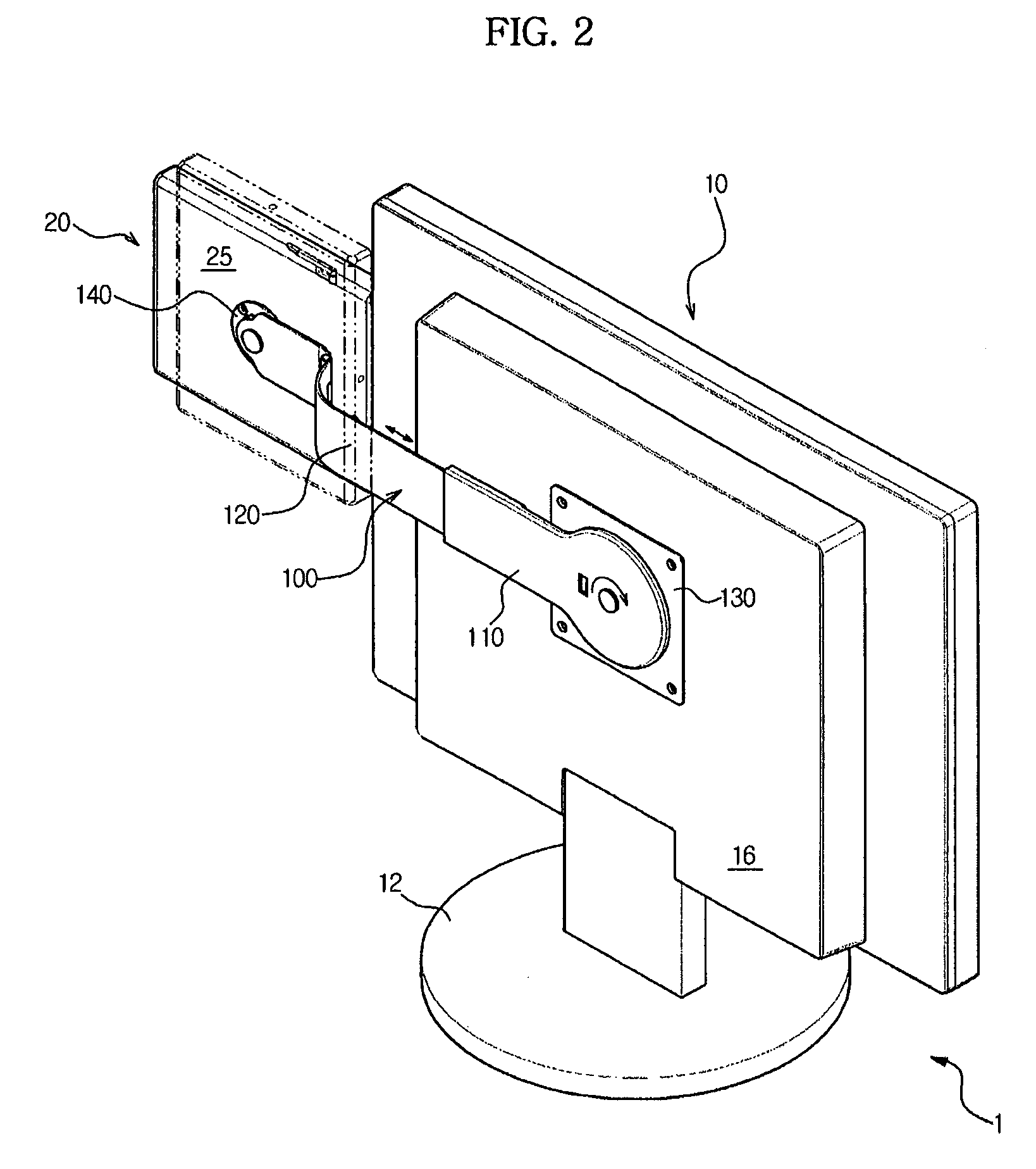
The present invention provides a supporting device that can change the position and pose of an auxiliary display unit relative to a main display unit. This allows for a variety of viewing configurations and makes it easy to add an auxiliary display unit to an existing display unit without increasing the thickness of the main display unit. The supporting device can be rotatably installed on a rear surface of the main display unit, allowing for portrait and landscape viewing configurations. The supporting device can include a first supporting member and a second supporting member, which are slidably coupled to each other to adjust the distance between the main display unit and the auxiliary display unit. The first supporting member can include a guide rail and a guide member to guide the sliding motion of the second supporting member. The second supporting member can include a hinge portion such that the auxiliary display unit is tilted forward and backward. The supporting device can be installed through an installation hole compliant with a VESA standard. The patent text also describes various ways to adjust the distance between the main display unit and the auxiliary display unit using the supporting device.

Problems solved by technology

However, the conventional dual display unit has the following problems.
Accordingly, the position and pose of the auxiliary display unit are very limited.
Further, there is a problem that the auxiliary display unit cannot be added to the existing display unit.
Further, since the receiving space which receives the auxiliary display unit and the moving unit which slides and moves the auxiliary display unit to change the position of the auxiliary display unit are provided on the rear surface of the main display unit, there is a problem of increasing a total thickness of the product.

Method used


Image

  • Supporting device and dual display unit having the same
  • Supporting device and dual display unit having the same
  • Supporting device and dual display unit having the same

Examples


Embodiment Construction

[0056]Reference will now be made in detail to exemplary embodiments of the present general inventive concept, examples of which are illustrated in the accompanying drawings, wherein like reference numerals refer to like elements throughout. The embodiments are described below to explain the present general inventive concept by referring to the figures.

[0057]Hereinafter, an embodiment of the present general inventive concept will be described in detail with reference to the accompanying drawings.

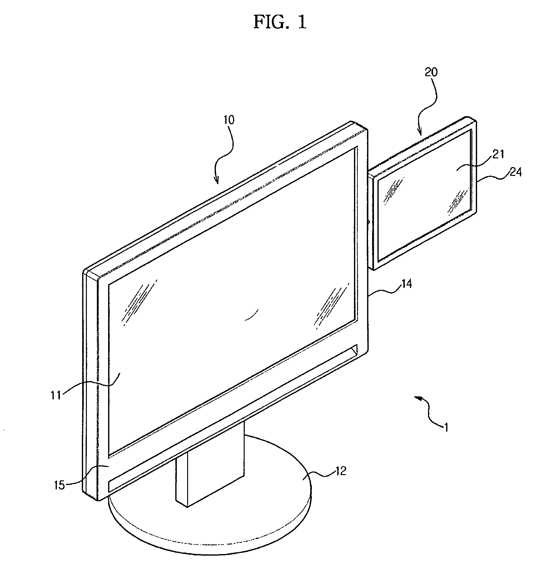
[0058]FIG. 1 illustrates a perspective view showing a front surface of a dual display unit 1 having a supporting device 100 (see FIG. 2) according to the present general inventive concept.

[0059]The dual display unit includes a main display unit 10 and an auxiliary display unit 20. The auxiliary display unit 20 is installed on a side surface 14 of the main display unit 10.

[0060]A stand 12 is installed at a lower portion of the main display unit 10 to support the main display unit 10 on a desk ...


PUM


Abstract

A supporting device is installed between an auxiliary display unit and a main display unit to variously change the position and pose of the auxiliary display unit and a dual display unit having the same are disclosed. The dual display unit includes a main display unit which displays an image, a supporting device which is coupled to the main display unit, and an auxiliary display unit which is installed on the supporting device. The supporting device is configured to adjust the distance between the main display unit and the auxiliary display unit.

Description

CROSS-REFERENCE TO RELATED APPLICATIONS[0001]This application claims priority under 35 U.S.C. §119(a) from Korean Patent Application Nos. 2007-0100113, filed on Oct. 5, 2007, and 2008-1492, filed on Jan. 4, 2008, in their entirety in the Korean Intellectual Property Office, the disclosures of which are incorporated herein by reference.BACKGROUND OF THE INVENTION[0002]1. Field of the Invention[0003]The present general inventive concept relates to a supporting device and a dual display unit having the same, and, more particularly, to a supporting device which is installed between an auxiliary display unit and a main display unit to variously change the position and pose of the auxiliary display unit and a dual display unit having the same.[0004]2. Description of the Related Art[0005]As multitasking using the computer becomes common, a dual display unit is increasingly desirable to provide various screens to the user through an additional display unit in addition to a basic display uni...

Claims


Application Information

Patent Timeline
Patent Type & Authority Patents(United States)
IPC IPC(8): E04G3/00H05K5/00
CPCG06F1/1601Y10T16/52
Inventor JUNG, JUN SULEE, JEONG ROHKIM, JIN SUNG
Owner SAMSUNG ELECTRONICS CO LTD
Learn More